The Raspberry Pi was inititally relesed for developers, to try gain suppoert from the development community. However, on release it targetted the market for hobbyists and young aspiring youths to gain knowledge and learn about programming.
The official Raspberry Pi website describes it as 'a low cost, credit card sized copmuter that plugs into a computer monitor or TV, and uses a standard keyboard and mouse'. They describe that it allows people of all ages to explore into computing and learn how to program in languages such as SCratch and Python. They say it's capable of doing anything a desktop computer can do from browsing the internet and playing HD videos, to making sreadsheets, word processing and even playing games.
In previous lessons you have worked on the main theory on how to get this project to work, but now we will be tackling the hardware. This lesson will be very much a practical lesson, so after we've gone through the basics we can get working on assembling the circuits.
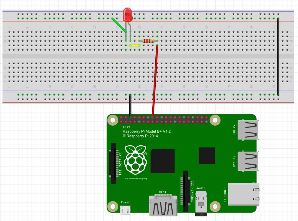
The circuit diagram below gives an overview as to what the circuit has to look like. The circuit is very simple so should not be difficult to assemble once you are used to it.
The way a headboard works is that the four rails at the top and bottom are connected horizontally, and the pins the middle are connected vertically, which is shown by the pins highlighted in green, in the diagram below.