
Final Product
Our clients tasked us with developing a smart-parking application, built upon the larger sensor network platform. The application was to indicate the state of street-side parking bays across london - where they were, how long they'd been occupied for, whether it was legal to park there, and more. Since starting the project, we've prototyped various hardare for parking bay monitors and produced a fully functioning web app.
Click here to try our smart-parking app
Of course, a lot of planning and design went into every aspect of this demonstration of the system in use. See below for a detailed analysis of how exactly we did it, and discover how the sensors network streamlines the development process.
Design
The parking app was to have a straight-forward UI with a focus on the map element. The use of the Google Maps JavaScript API was identified very early on, with the clients specifying that they'd like to be able to see coloured icons indicating the state of parking bays. For the purposes of demonstration, we also opted to show additional data for each parking bay in a static panel on the left-hand side of the screen, as can be seen here.
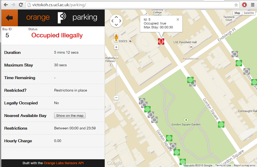
The final front-end design of the Smart Parking app.
Ideally in a future iteration, we'd like to have this information panel cut down and shown in a neater infoWindow instead. It's important to note here, too, that we've used AJAX calls using the JQuery library to efficiently and automatically update the bays in real-time. This means that, at most, there will be a gap of 3 seconds between a reading being added to the database and the icon changing to reflect that. Here's a brief extract of the code we used for updating each bay with the appropriate icon.
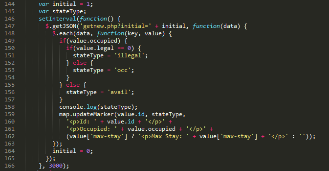
Javascript code for updating the bay icons.
We also used custom-designed icons for indicating the bays as indicated by this legend.
The custom icons used in our application to indicate the state of a given parking bay.
Hardware
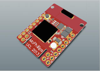
The MC1322x micro-controller
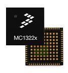
For our project we decided to go with a MC1322x micro-controller. This controller was developed by Freescale as a tool for handling small scale ZigBee communications and sensor control.
The reason for choosing this specific controller was because early research showed that it was compatible with Contiki, which we were planning to use. Our professor Graeme McPhillips created a board around the controller to allow us to access the different ports more easily. The board is shown below:
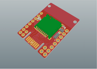
For full documentation on the mc1322x refer to the documentation pdf
For full documentation on the Stamp board refer to the documentation pdf
Contiki
Contiki is the software we used to control the micro-controller. The basic idea of Contiki is to provide a set of libraries to take care of low level control of the microcontroller. It skips the step of configuring every input and output of the device so that we are left with easy to use functions for operating ADC inputs and ZigBee.
For full documentation on Contiki, refer to their website: http://www.contiki-os.org/
Infra-Red
For our project we went with infra-red to determine the state of our parking bay. Infra-Red allows for a low cost, easy to implement way of determining the state of a car simply by reading a distance measurement.
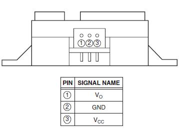
The below sensor is the one we used for our project. It is called the Sharp 2Y0A02 Distance Sensor:
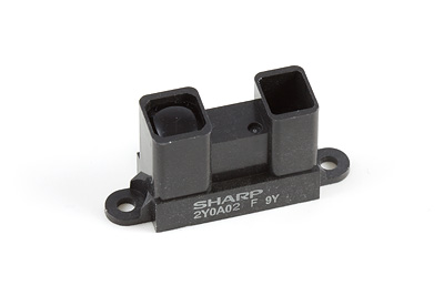
For full documentation on the device refer to the documentation pdf
Control of this device is done via Contiki and the micro-controller, which is shown in our tutorial section.
ZigBee
For our project we went with ZigBee to handle communications between the different sensor units. It does not handle communication with the Arduino, as that is done with a simple serial connection.
We went with ZigBee, because it is designed for low power use cases like ours and the Contiki library allowed for easy implementation of this.
It is the ideal communication protocol for this kind of project, as the range is well within what would be required for parking applications. For use cases unrelated to parking and where distances exceed ~100m per sensor, using other communication devices is recommended.
For our project we went with ZigBee to handle communications between the different sensor units. It does not handle communication with the Arduino, as that is done with a simple serial connection.
For full documentation on ZigBee, refer to the documentation pdf
Arduino

We used the Arduino in our system to act as our zone controller. For the sake of demonstration, we had to handle global communication via a computer due to the service being down for the shield we were planning to use. We used the Arduino Mega along with a Arduino GSM shield:
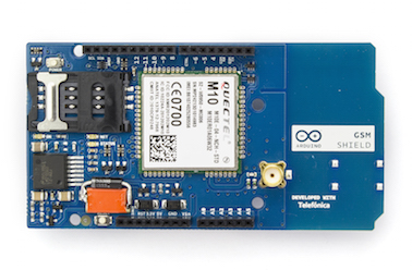
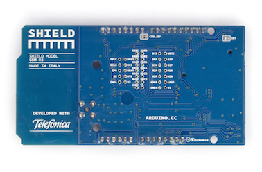
In a real life implementation of this project, it is recommended to use something smaller than the Arduino, as it draws unnecessary amounts of power. The best thing to do would be to attach a GSM shield directly to your sensor unit, instead of using the Arduino as a medium. For the sake of simplicity we chose to use Arduino.
For more information on Arduino, refer to their website: www.arduino.cc
Using the Java API for analytics
The general process carried out for analytics is as follows:
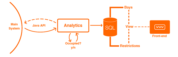
High level abstraction of Analytics
The CQL database is accessed twice making use of the JAVA API built, data gained from this is processed in the class named 'Analytics' and whether a change of state has occurred along with its associated timestamp is uploaded to a separate SQL database hosting parking information. Two tables within the parking database are then used to create an SQL view where additional time-based analytics is carried out. Finally, this information is displayed on the front end parking app by making use of a mixture of javascript and PHP.
There are three primary Java classes involved in carrying out the back end analytics for the smart parking app.
These are:
-
Bay -
For creating Bay objects. The number of objects initialised within the Parking class correspond to the number of Bays within the SQL database 'orangeparking'. This class extends the observable design pattern and is used to notify the Analytics class's observer when a change in state (occupied/ unoccupied) has occurred so an update to the SQL database can occur. -
Parking -
Makes an initial connection to the SQL database to retrieve an initial set of data on all bays present. It also includes an update function which accepts a bay object, creates a new connection and updates the bay_data's occupied and state_timespan fields based upon bay_id. -
Analytics -
This class represents the main thread running analytics. An initial call is made to the CQL database making use of the JAVA API built. This collects the set of all sensor ids (global_ids) of which matches the Bay objects. A second call to the CQL database is then made via the API. Given the new time stamp retrieved differs from the previous reading's, an assumption is made that an update in the actual CQL database has occurred for that specific sensor id associated with a bay. Whether it is occupied or not is then worked out via the sensor reading retrieved. This then calls the specific Bay object's setOccupied function and the SQL parking database is updated using the Observer pattern.
At present, the majority of analytics is performed within a read-only SQL view table.
There are two key reasons for this choice. Other than calculating whether a bay is 'occupied' (1 | 0) and the time this state change occurred, all other information of interest to be displayed on our web app is already implicitly known and can be calculated
in a less resource heavy fashion. Views also update via lazy evaluation, 'on the spot' when called by PHP server-side code on our web app. This is better suited for our purposes as calculations such as 'time remaining' only occur when they are needed (the website is accessed by a user) and are not
calculated continuously in the background.
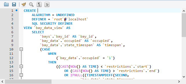
Code snippit from the SQL view
The information provided within the view table includes:
-
The nearest available bay
This is worked out given the current state of a bay. If a bay is unoccupied, then it itself is its nearest available bay. Consequently, given a bay is occupied, a list of all unoccupied bays within the area are found and making use of the euclidean distance formula in 2D, the next nearest available bay is identified. -
Time remaining
Given a restriction_id and that max_stay is not NULL within the restrictions table of the SQL Parking database, Time remaining represents the amount of time left (in seconds) one can be within an occupied bay state while still being 'legally parked'. Likewise, this is only calculated if a bay is occupied. Otherwise if it is unoccupied and max_stay does not list a time restriction, it is set to NULL. -
Legally occupied
The legally occupied field is calculated based on three different conditions. Provided a bay is indeed occupied: If the current time of occupation exists outside of the restriction start and end timings, no restrictions apply. Else if occupation occurs within restricted hours, given the time remaining in seconds when the difference is taken from max_stay is still positive, legally occupied is set to true. Otherwise, it is set to NULL.
-
Restricted
Calculates whether restrictions are currently active for a specific bay (joined to a specific restrictions_id)
Simulating Sensors
Manual Simulator
Feel free to download this sample simulator for sending single values to the server. Follow the video on the Showcase page for a guide on how to get started!
Download the manual sensor simulator
Threaded Simulator
In order to test our system, and since we didn't have the hardware capabilities available to us, we produced automated sensor simulator software. This had a simple design, whereby a sensor would be represented by a single thread operating separately from the others. Each thread would wait for a normally-distributed amount of time, with a mean of 20 minutes and a standard deviation of 10 minutes. If it was then changing state to occupied, it'd send a random value between 20 and 30cm. Otherwise, it would send a value between 70 and 90cm. We used this to run 10 sensors over many days in order to test the longevity of the system - everything worked without any issue. It's important also to note that these were sending data in exactly the same way the hardware would - as a UDP packet in the same format.
The code for the simulator threads can be seen below
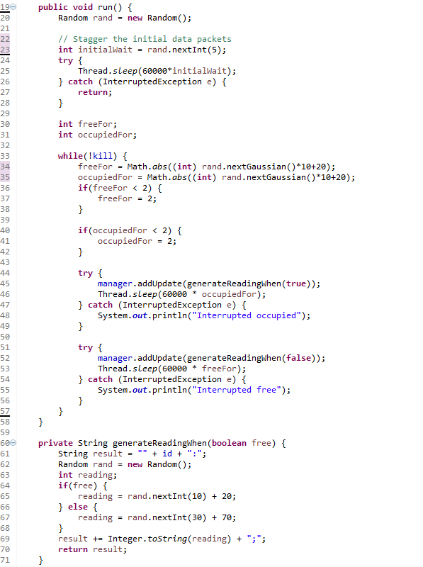
The main bulk of the code running the sensor simulator thread.