Hardware
In order to create a heart rate monitor, we will be making use of a pulse sensor. The program will input light sensor readings into the Engduino and measure the variations in order to count the number of heart beats over the time of one minute. To learn more about the pulse sensor, please access the official webpage for the piece of hardware. There, you can also find a video on getting started with it, and setting it up.
Actions
For this part of the project, we suggest creating a separate action, called pulse. This action will read the pulse from the sensor, print it out on the screen and, then, print out advice, according to the printed value.
Libraries
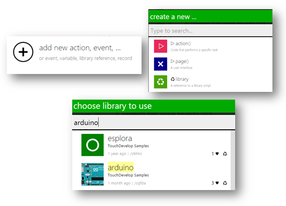
In order to include a new library to your project, tap the add new action, event,… button, and pick the option library, then search for engduino, and arduino and include them.
- engduino – in order to use the functions on the Engduino board, we will need to include the engduino library
- arduino – in order to access the pins on the Engduino board, we will need functions from the Touch Develop Arduino library.
By creating a blank engduino script, you have automatically included both of these libraries.
Programming Steps
1. Setting up the pin
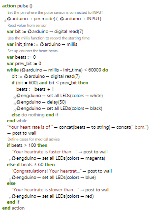
While setting up the hardware for this project, we suggested connecting the Pulse Sensor to pin number 7 . Therefore, in this part of the code, we will need to access that specific pin. In Touch Develop, this is done by typing in the following line of code:
arduino -> pin mode(7, arduino - > INPUT)
This particular line of code sets the specified pin to input mode, allowing the program to receive input from the piece of hardware connected to it.
The opposite is also possible if you connect output components to a pin (e.g. LEDs, motors, etc.). For this project, however, we will only need the input function of a pin.
2. Saving the value
Having set our pin as an input pin, we can now save the value it sends into a variable. For that, we will make use of the digital read function in the arduino library. We will define a new variable, called bit, for example, and store the sensor value into it.
var bit:= arduino -> digital read(7)
After having saved the value, we will print it out on the screen, in an infinite while loop.
while(true)
| bmp -> post to wall
| bit:= arduino -> digital read(7)
end while
You are already familiar to the post to wall function. Now, if you run the program at this stage, you will see a set of numbers, ranging somewhere between 400 and 600 – the light level detected by the sensor. To learn more about how this sensor works, you can check its website.
3. Calculating Heart Rate
If we were to graph these numbers, they would look something like this:
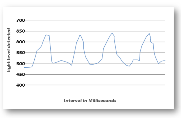
The fluctuations in the graph represent each heartbeat. In order to count the number of beats over the amount of one minute, we will make use of the function millis which counts milliseconds. The function millis accesses the virtual time recorded by the machine. Therefore, before starting to count, we will store the initial time in a variable, and then enter a while loop, where we will set up the count, while millis-initial_time<60000 the equivalent of a minute in milliseconds).
var init_time:=arduino->millis();
var beats:=0;
var prev_bit:=0;
while arduino->millis()-init_time<60000
|     bit := arduino -> digital read(7)
|	  if bit=600 and bit
|	  |       beats:=beats+1
|	  |       engduino->set all LEDs (colors -> white)
|     |       engduino->delay (50)
|	  |       engduino->set all LEDs (colors -> black)
|     else do nothing end if
|     bit->post to wall
|	  prev_bit:=bit
End while
“heart rate"->post to wall
“Your heartrate is of ” -> concat(bit - > to string) -> concat(“ bpm”) -> post to wall
One easy method of counting the number of heartbeats would be incrementing a variable by one, each time a value close to the maximums is reached. For this graphic example, a good value would be 600. This will take a bit of testing on your part, to decide on an appropriate number. But the number will be read both when the graph is going up, and down. Therefore, we will only count the 600s while going down (hence, the comparison to the previous value).
4. Creating different cases, for different ranges of values
We will now define a number of cases, each used for printing out a different piece of advice. In order to implement these cases, we suggest using a series of if statements.
You can find a list of basic cases below. However, we do not claim them to be specifically accurate. We strongly advise you to research the topic and create appropriate medical advice of your own.
| Heartrate Range | Medical Advice |
|---|---|
| >100 | “Your heartrate is faster than the recommended range. You might be experiencing a case of Tachycardia. We strongly suggest getting a doctor’s opinion.” |
| 60 – 100 | “Congratulations! Your heartrate appears to be within the recommended bounds.” |
| <60 | “Your heartrate is slower than the recommended range. You might be experiencing a case of Bradycardia. We strongly suggest getting a doctor’s opinion.” |
if(beats>100)
|	“Your heartrate is faster than the recommended range. You might be experiencing a case of
Tachycardia. We strongly suggest getting a doctor’s opinion.” -> post to wall
|	engduino -> set all LEDs (colors ->magenta)
else if(beats>=60)
|	“Congratulations! Your heartrate appears to be within the recommended bounds.” ->
post to wall
|	engduino -> set all LEDs ( colors ->blue)
else “Your heartrate is slower than the recommended range. You might be experiencing a case of Bradycardia. We strongly suggest
getting a doctor’s opinion.” -> post to wall
|	 engduino -> set all LEDs (colors ->red)
end if
Final Code
Plain text file containing the final version of the code for the heartrate monitor.
This is the end of the Pulse Section of your project.
However, you are welcome to come up with new ideas and improve it!
Additional Exercises
- Tidy up the code for this part, creating separate actions for each small bit. You can check the Temperature Section for an example of how this can be done.
- Further improve this script by having the Engduino LEDs display how high one’s pulse is, increasing the number of lit up LEDs as the counter gets
incremented. You can use different colour combinations to display medical indications (e.g. turn the LEDs red when the pulse is higher than the recommended
range).
Example: If, at some point, the counter shows that the pulse is 10, light up only one LED, and make it a specific colour (e.g. blue). Then, if it increases to 20, light up another LED of the same colour. When it gets to 60, it will light up 6 LEDs, and turn all 6 of them white. Furthermore, it gets above the recommended range of 60-100, light up the appropriate amount of LEDs, and turn them a different colour (e.g. red).