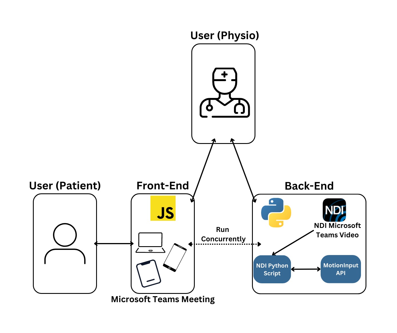
System Architecture
Our current Teams solution has 2 main components. Users can interact with the application frontend, inside a teams call, where they can play games. The backend is the NDI MotionInput solution, where camera streams are extracted from a Microsoft Teams call and fed into MotionInput. Our high-level system architecture containing these components is displayed:
Context Diagram
This Context Diagram is an extremely high-level visual representation of the solution and its core functionalities. It provides a simplified view or the data flow in the system, and helped other teams who we collaborated with, to understand our system at a high-level.
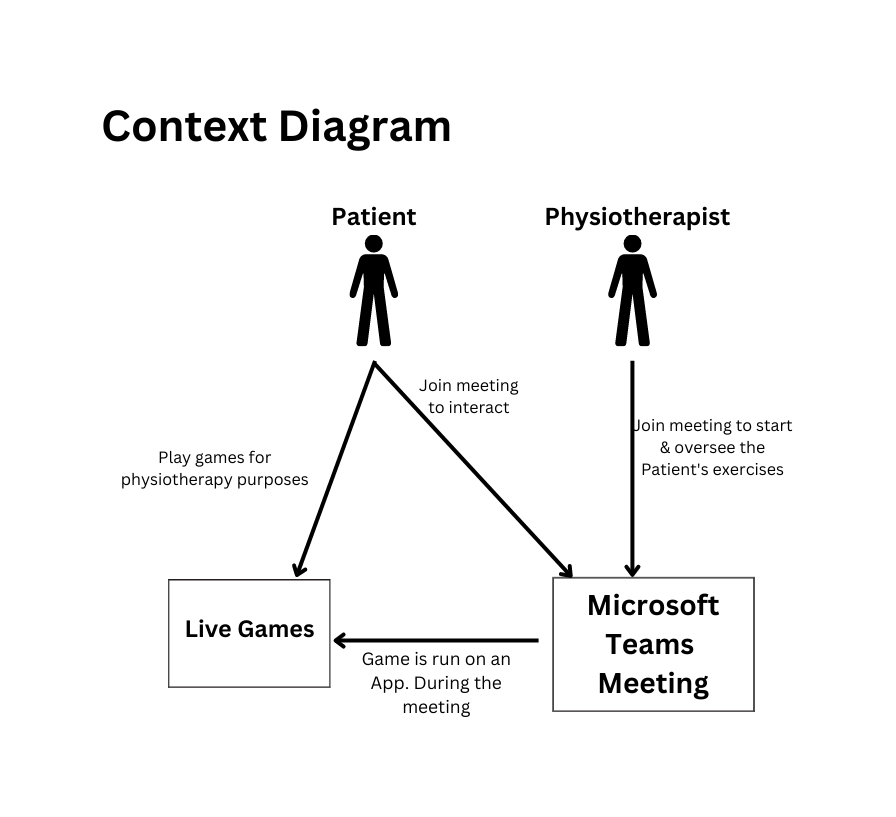
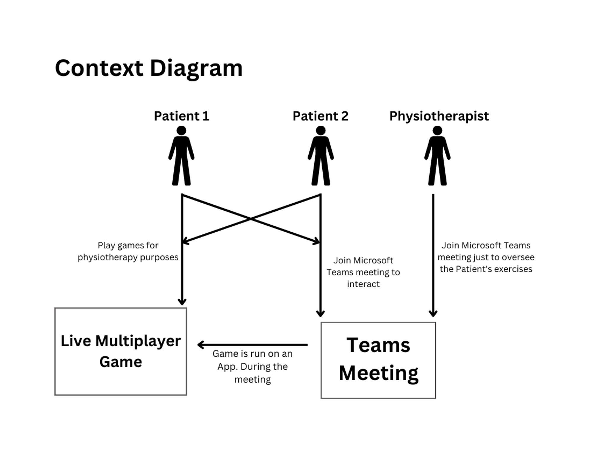
Having also built a collaborative framework based on Live Share SDK, we created an updated Context Diagram, based on this newly released technology, seen on the right.
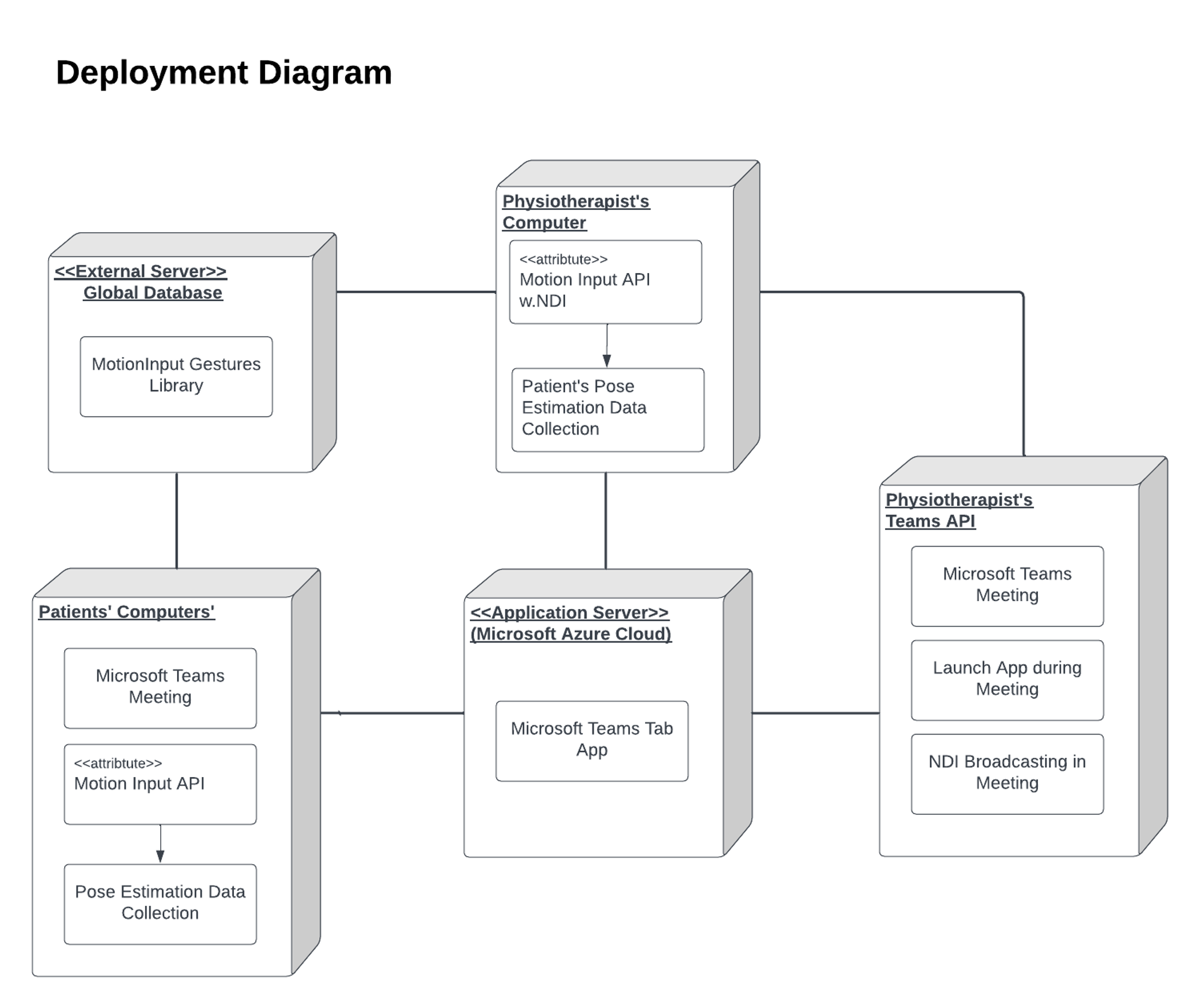
Deployment Diagrams
A deployment diagram is a type of UML diagram we used to depict the physical architecture of our system. It helps visualise the interrelationship between hardware and software by displaying various hardware devices and softwares distributed across different nodes. The main purposes of utilising this diagram is to aid designing, analysing and communicating the system architecture. As well as, verifying system requirements for our own personal use.
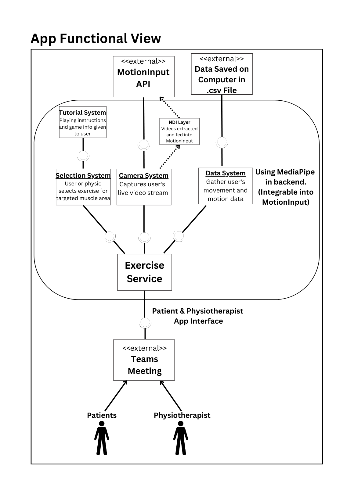
Functional View
The App Functional View Diagram helps illustrate the functional requirements of our whole system. As well as providing a high-level overview of the data flow; the main components of the system and how user’s can interact with these subsystems. By breaking down complex systems into manageable parts, to allow us to manage and design the system. Furthermore, the diagram displays requirements covered and provides a visual representation of how data moves through the system.
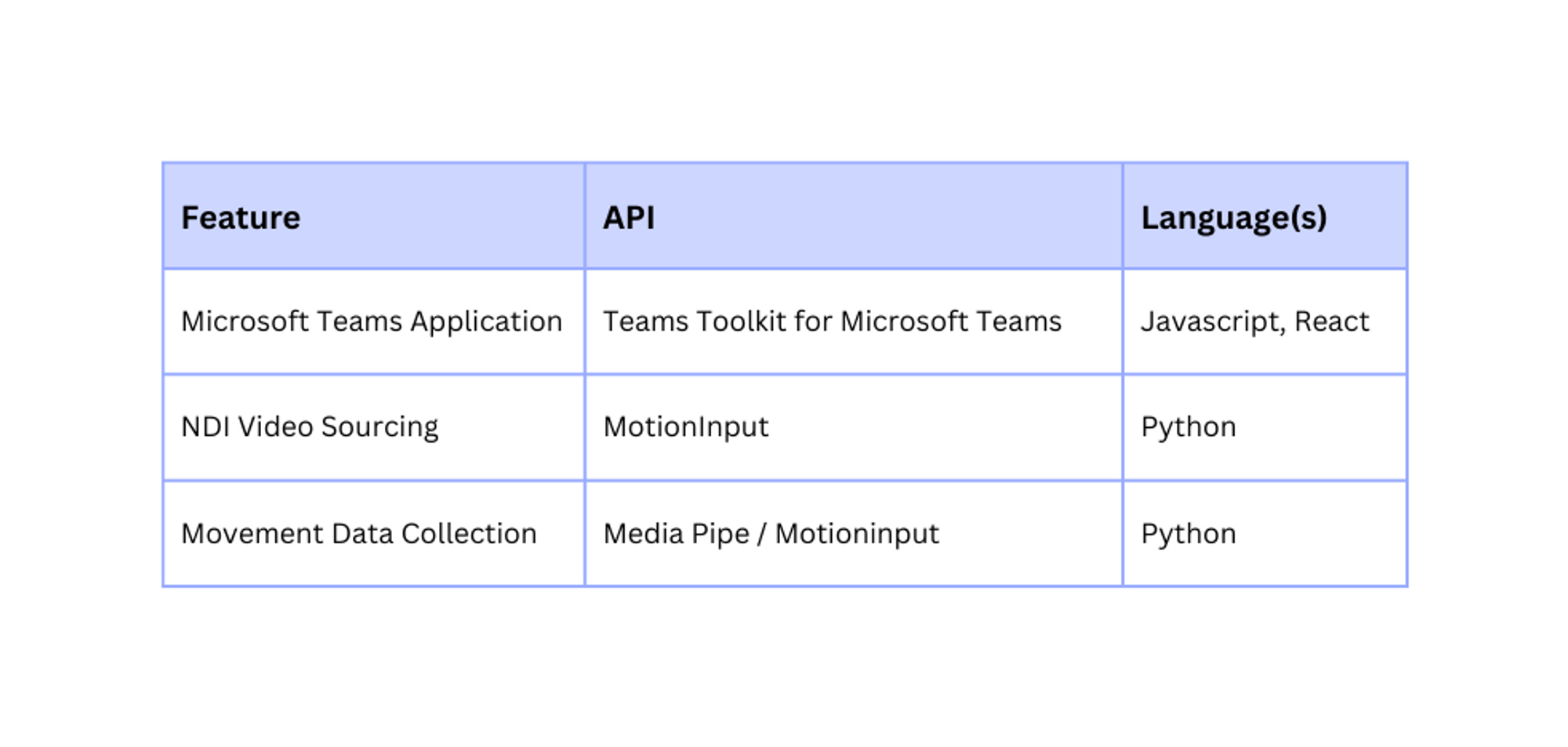
Packages & APIs