System Launcher
The system launcher, UCL Open-Illumiroom V2 Launcher.exe, is the point of entry for the UCL Open-Illumiroom V2 system for users.
Users use the launcher to:
- Select their displays.
- Calibrate their setup.
- Select their required projection mode.
- Change certain mode and general settings.
- Start and stop the display of projection modes on their projector.
Changing settings on the MFC causes the settings to be updated in the general_settings.json and mode_settings.json files. Clicking Select Displays, Calibrate System and Save and Launch causes the main system app UCL Open-Illumiroom V2.exe to be run (located in the UCL Open-Illumiroom V2.dist folder).
Different parameters are passed in during the system call to run the app. Based on the parameter passed, a different version of the app is run. As a result, all functionality of the system can be included in the UCL Open-Illumiroom V2.exe, each of which can be called separately.
| Action | CMD Command |
|---|---|
| Run UCL Open-Illumiroom V2 projection modes |
start UCL_Open-Illumiroom_V2.exe
|
| Select displays | start UCL_Open-Illumiroom_V2.exe display |
| Run calibration | UCL_Open-Illumiroom_V2.exe calibration |
The MFC can also close the projection by killing the UCL_Open-Illumiroom_V2.exe task.
The system launcher was developed as a Microsoft Foundation Class (MFC). MFC was used as a library, rather than other libraries for designing desktop apps such as .NET so that the system can be run without installation on older devices/versions of Windows frequently used in hospitals for use in healthcare settings. A video demonstration of setting up the UCL Open-Illumiroom V2 and calibrating using the MFC can be seen below.
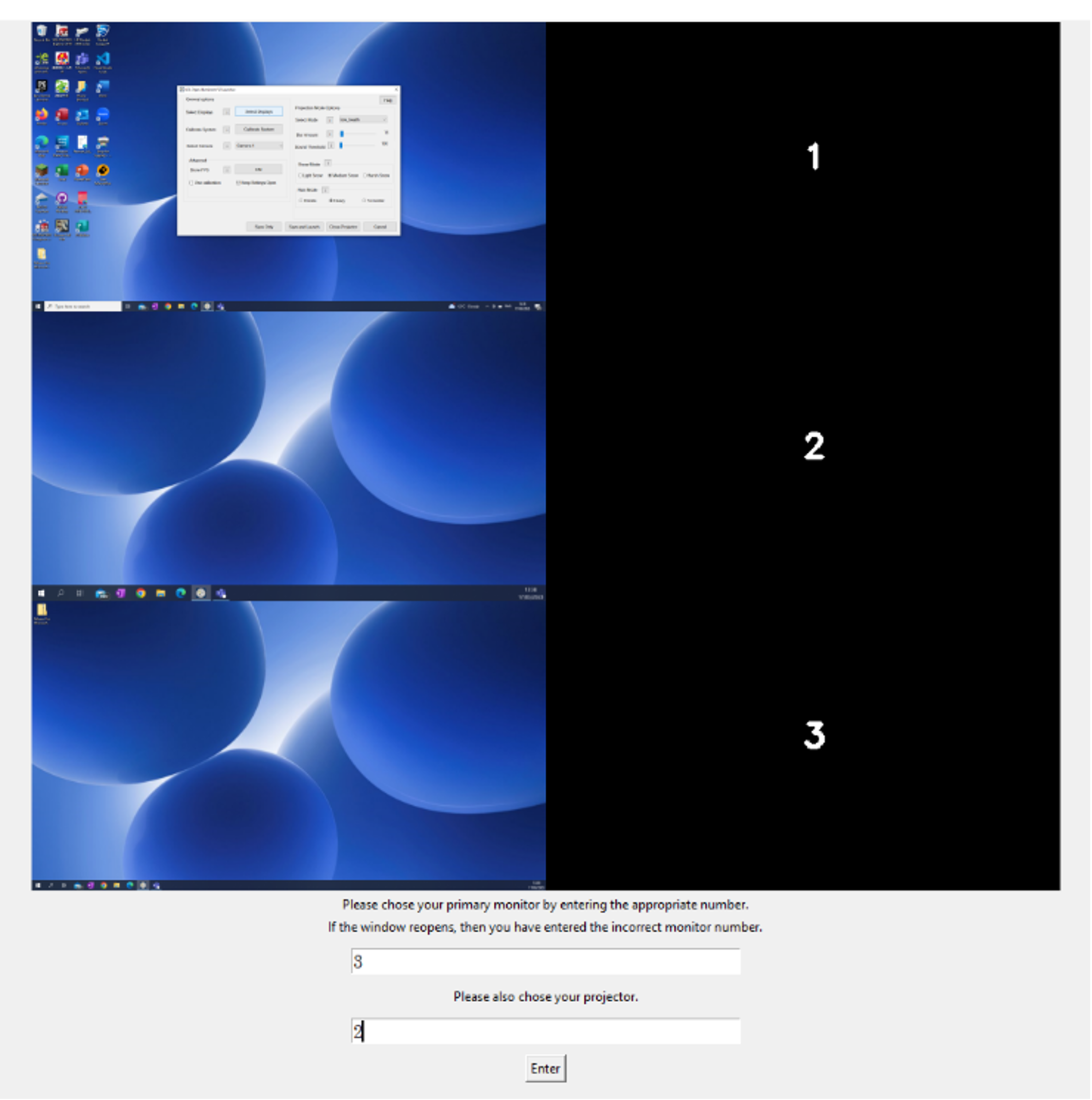
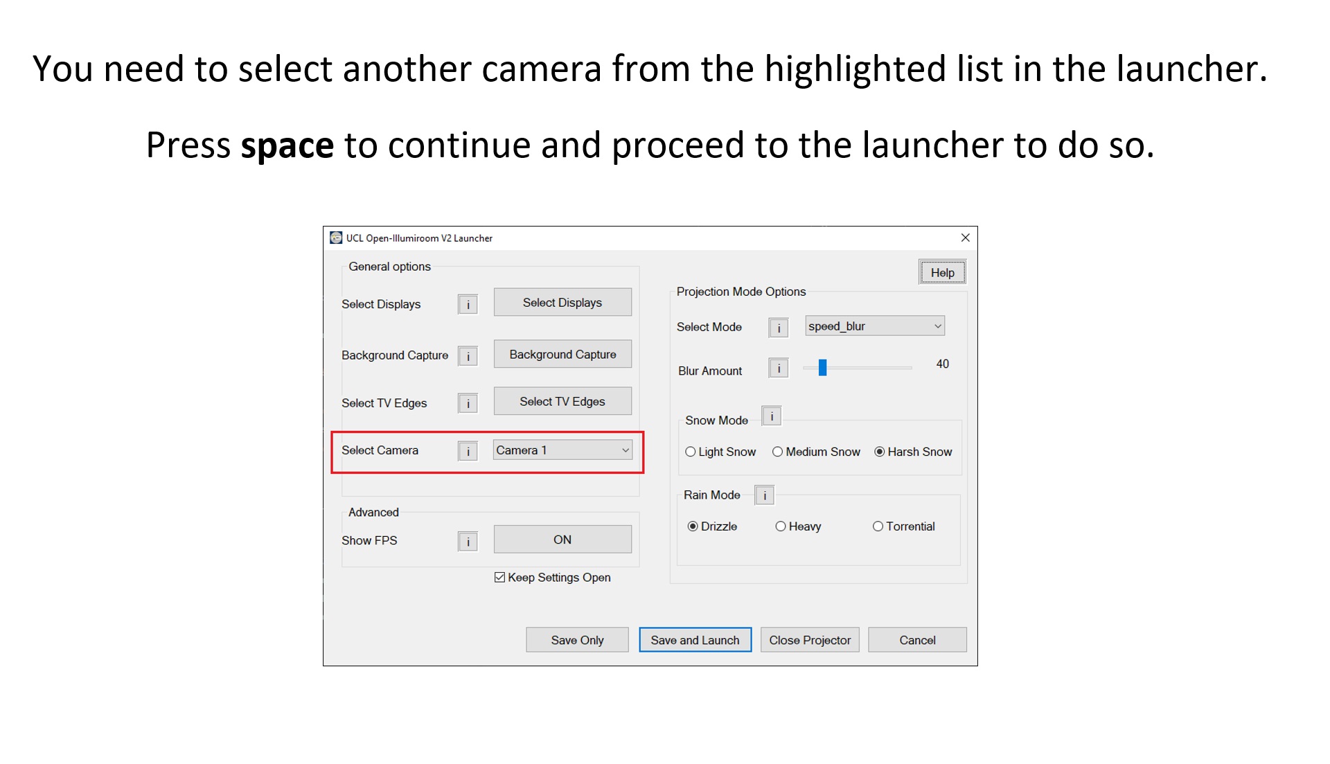
The following image shows how the system launcher MFC window looks.
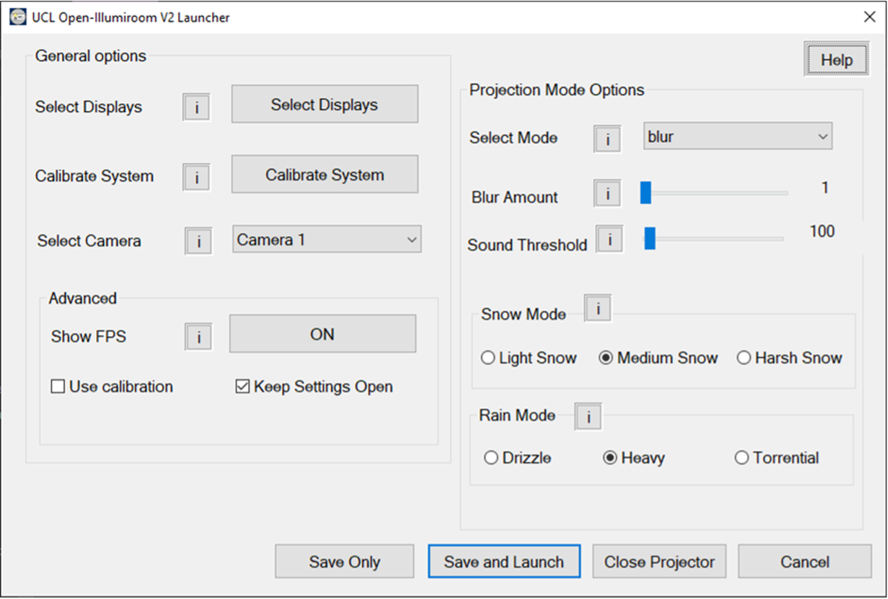
To improve the system launcher, more settings could be added, especially related to the projection modes to increase customisability. These could have been added in submenus, divided by the mode name. The launcher does not match the prototyping we did during the Requirements phase due to the limitations of and difficulties with using MFCs.
Projection Modes
The UCL Open-Illumiroom V2 displays frames generated by projection modes on the projector. As explained in our System Design, each projection mode inherits the behaviour from a Mode superclass. This along with the Mode Factory allowed us to easily extend the system each time we built a new projection mode. Here is an explanation for the implementation of the each of the final projection modes.
Blur
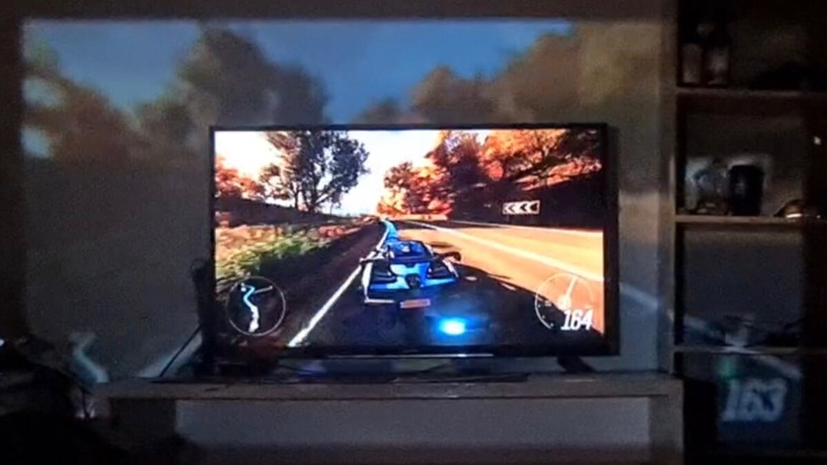
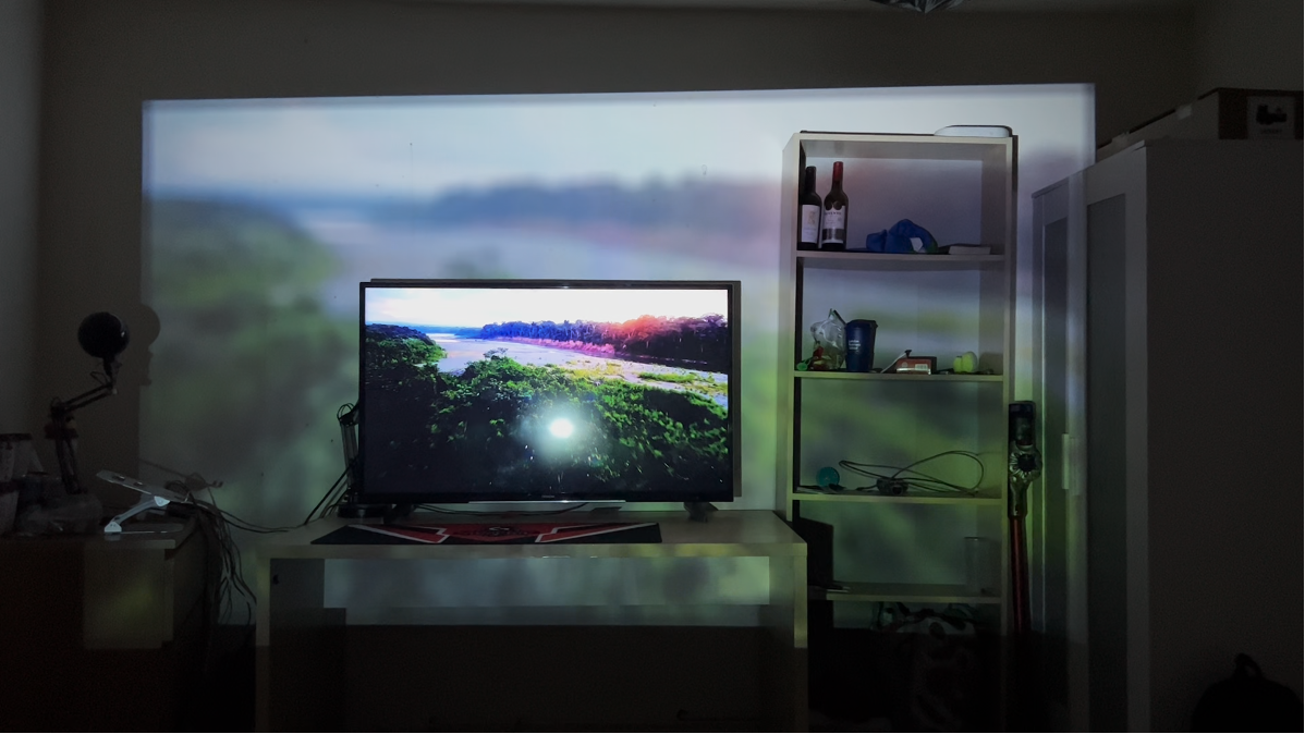
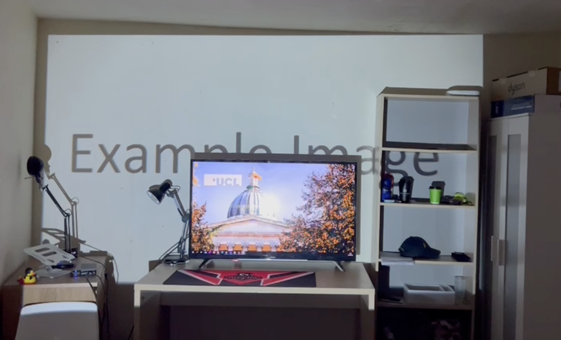
The Blur mode simply projects a blurred version of the content shown on the primary display. This mode is very simple and can work well with almost any input media. It creates an especially immersive effect in games that involve racing cars, since the projected visuals at the edges of the TV screen appear to come out directly from it. Blur works well with nature documentaries, especially with movement, since your entire projection space can be filled up with the beautiful natural scenes.
In terms of the implementation, this mode requires very little additional context, and simply uses the display_capture util to capture a frame from the primary video feed, blur it, then display it on the projector. Unlike some of the other modes, it does not apply the effect onto the image captured of the projection area.
Speed Blur
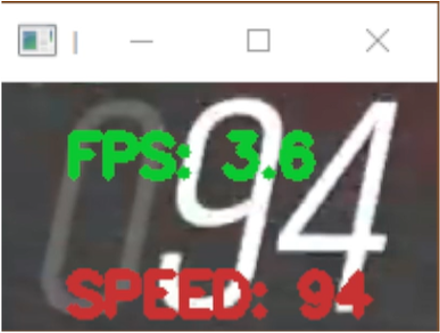
The speed blur mode has been designed to work in Forza Horizon 4, however it can easily be adapted to work for other racing games. The mode uses Pytesseract’s Optical Character Recognition (OCR) model to recognise the speed shown on the player’s speedometer. The speed information could be used to generate any of a number of effects, such as lines which come out of the TV screen at higher speeds. However, our implementation simply blurs the screen based on the player’s speed. Unfortunately, due to limitations with processing power, the frame rate for the mode is currently very low, this could potentially be improved with better use of threading and multi-processing.
The image below shows an example of the model detecting the speed of 94 from the speedometer. The model’s prediction is shown by the red text.
An early demonstration of the speed blur effect is shown in this video. Instead of blurring the screen, the colour of the projection changes from red to green, based on the player’s speed. The software was later refactored and changed, to instead display the Speed Blur mode. The blurring uses the same OpenCV blur function as the Blur mode. Here is a video demonstrating the previous iteration of the mode.
Low Health
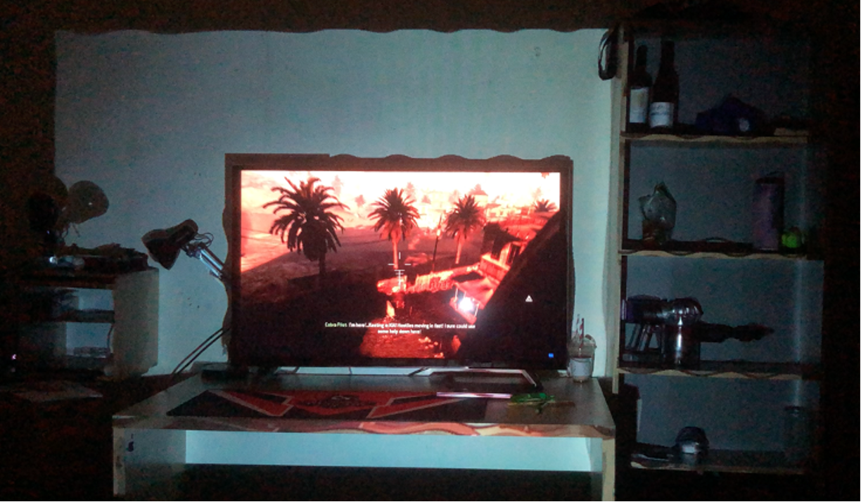
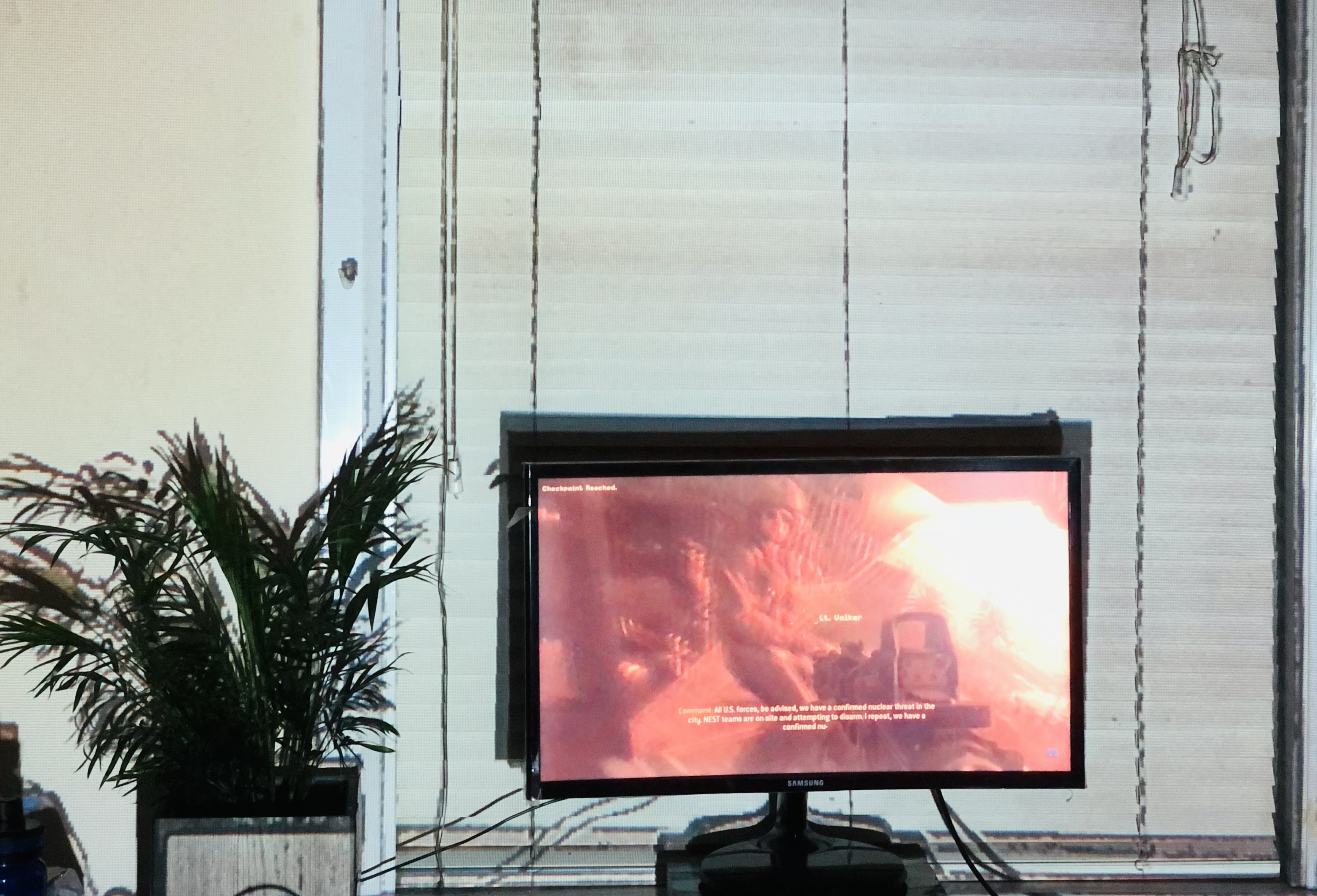
The low health mode makes the projection area turn red when the player is on low health in a first-person shooter game. Using the k-means clustering algorithm in OpenCV, the average colour is calculated, and the red channel is compared against the blue and green ones. The method to calculate the average colour was taken from Giovanni Code’s video Dominant Colors Extraction with OpenCV.
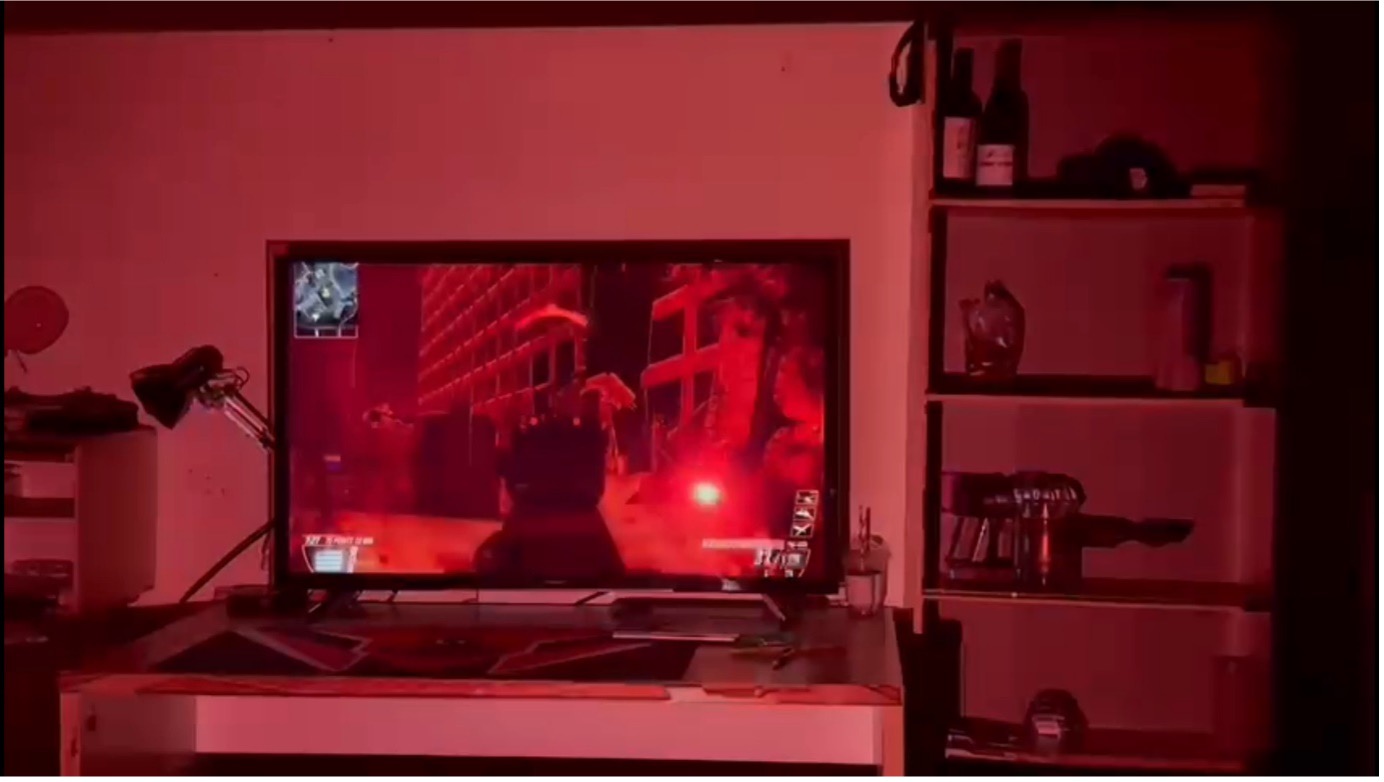
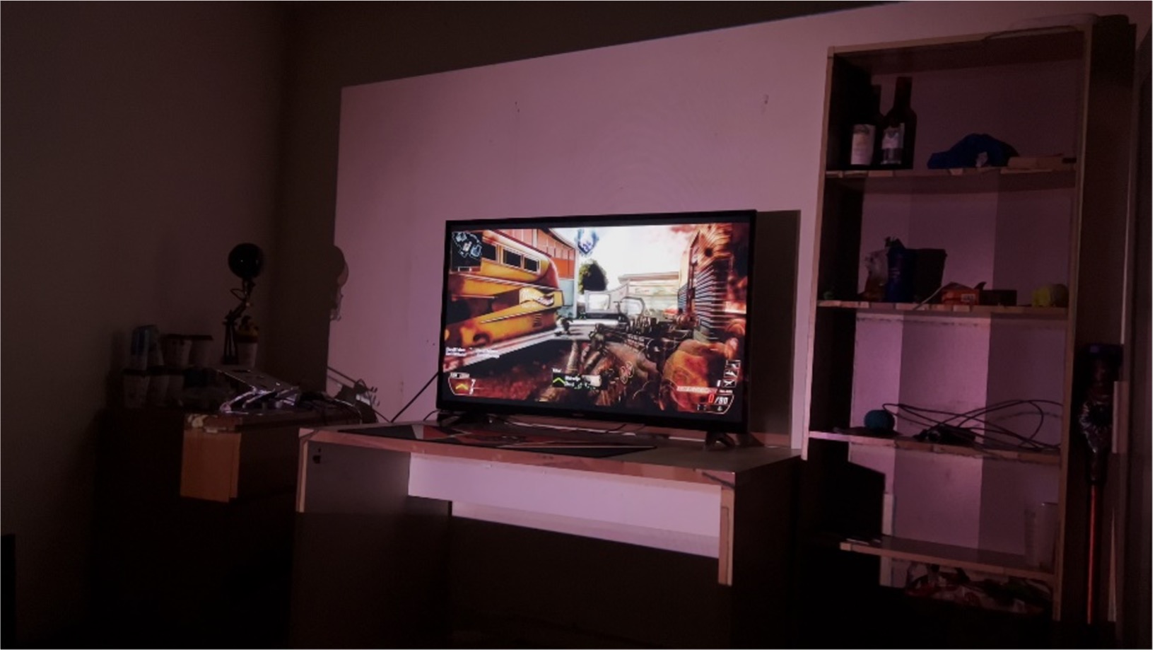
If the red channel of the screen’s dominant colour is high enough, red effects of varying hues are displayed on the wall, indicating to the user that they should take cover and heal up. The colour of the effect is scaled to the red channel, the greater the channel, the deeper the red. This is an especially helpful cue for those who may struggle with their vision, since the effect is bright and visible on the wall, and highlights that the player should take cover to recover their health.
Here is a development log video further demonstrating how the Low Health mode was developed. This can also be found on our development blog. A video demonstration of the mode is also shown below.
Wobble
The Wobble mode triggers a sinusoidal distortion centred around the TV screen whenever an explosive sound is detected. It works for any game or film as we currently record the audio using the laptop’s microphone and analyse it. Based on the specified number of frames for the distortion (the more frames, the smoother the animation), each frame in the effect is generated like this:
- First, a mask is created to exclude the pixels inside the TV in the animation.
- The distortions are centred around the centre of the TV so the distance between the centre and each pixel is calculated. This, along with the amplitude and frequency of the wave motion, help in figuring out the coordinates of the new pixels.
- To ensure that the animation comes to a stop how it started, with the geometrically transformed pixels in their initial positions, we have used an interpolation factor to interpolate between the new pixel coordinates and the initial coordinates. Without this interpolation, the animation would abruptly stop, producing a jarring visual effect.
- We generate an image frame of the new pixel coordinates using OpenCV’s
remap. This frame is appended to the list of available frames.
Some optimisations we have performed to increase the animation quality:
- Utilising an interpolation factor for a smoother animation.
- Storing the pixel coordinates for the image in a NumPy
meshgridinstead of using nested for loops to reduce the time complexity and speed up the frame generation.
A demonstration of the Wobble mode is shown in the video.
We have written the code to read the system audio by using Python's SoundCard package since analysing the microphone audio introduces scope of error. However, we are unable to incorporate this into the final build as Nuitka doesn’t yet support SoundCard compilation. This could be overcome in the future by translating the production code from Python to C++, bypassing the need for Nuitka.
DisplayImage
The DisplayImage mode simply projects a specified image that has been pre-generated and stored in the assets/display_image folder. This mode is useful for demonstrations and mock ups of modes. The mode could also be used for creating static displays. It could be extended by displaying pre-recorded videos instead of still frames.
Cartoon
The Cartoon mode works by projecting an image of the room with the edges of the furniture coloured black. Using the image of the projection area, the cartoon effect is generated with the CV2 library.
- The image is converted to grayscale.
- A slight blur is applied to remove the effects of noise.
- The edges in the grayscale image are detected using cv2.adaptiveThreshold and converted to a colour image format where the edges are coloured black.
- The original image of the room is merged with a filtered colour image of the detected edges.
Since the cartoon mode is simply a static filter, this image is saved locally and loaded whenever the cartoon effect is applied to increase efficiency.
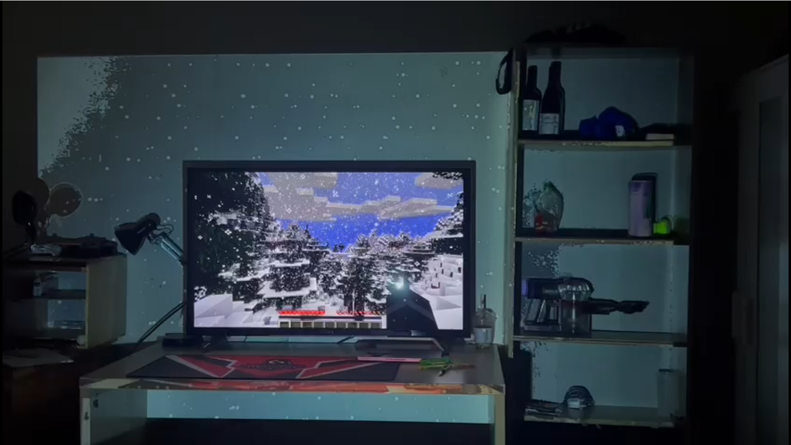
Snow
The Snow mode generates a falling snow effect where the user can switch between light, medium and harsh snow. The snow falls from the top of the screen and moves down based on a defined falling speed and noise wind. To enhance the animation, the radii of the circular snowflakes also change as they fall. For the snow mode, the snow also appears to settle over time. To achieve this, the image of the room is converted to a HLS format (Hue, Lightness, Saturation). The brightness of the image is increased slightly to reduce the effect of the low-light conditions of the room. Then, the Lightness value is increased, whitening the darker parts of the image e.g., areas where there are shadows. Below is a demo of the Snow mode on the harsh snow setting.
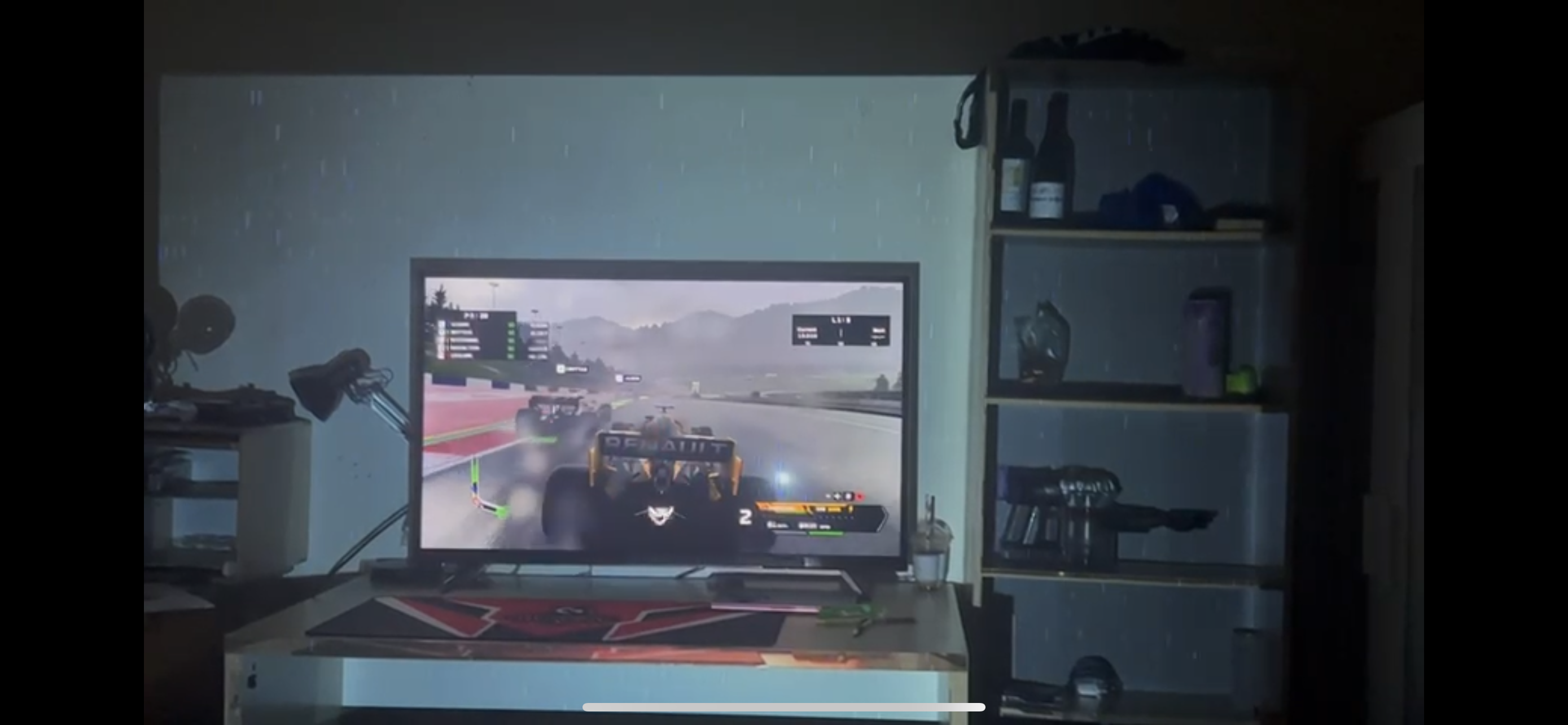
Rain
The Rain mode generates a rain effect from the top of the screen where the user can switch between drizzle, heavy and torrential. To make realistic rain, the length and the colour of the rain drops change as they fall. This idea has been adapted from the effect achieved by the changing snowflakes in the Snow mode, as explained above. As the raindrops are all different shades of blue, the mode gives off a damp feeling to the TV's surroundings.
Weather
The Weather mode automatically detects the weather in scenes of media on the primary display and can change the weather effect displayed on the projection area. Currently, the system supports changing between the Snow and Rain modes.
The mode works by capturing the screen and classifying the weather in each frame. The method for doing this takes a frame argument, which is an image (in the form of a NumPy array). The image is first flipped along its RGB channels (since Keras expects images in RGB format, but OpenCV reads them in BGR format by default), and then resized to a 64x64 pixel image. The pixel values of the resized image are then normalised to be in the range [0,1]. The pre-processed image is passed to the pre-trained model to obtain a prediction, which is a probability distribution over the possible weather conditions.
The predicted class index returns the index of the highest probability value in the predictions array. Finally, the predicted class index is used to return the predicted weather condition as a string. If the predicted class index is 0, the method returns "cloudy"; if it is 1, it returns "lightning", and so on.
Unfortunately, the model is not perfect and sometimes classifies blank black/white screens as rain and snow. Future versions of the weather mode could use improved machine-learning models to classify the weather. Also, more weather modes could be created, such as a Lightning mode for when lightning flashes across the TV screen.
Utils
Display Selection
The DisplaySelection class is used for selecting the correct projector and TV displays during the system setup. The user is presented with a dialogue showing all currently available screens, their indices, and contents. The user needs to match the displays to the correct index value so that the primary screen and projector display can be identified. After the user confirms their choice, their response is saved locally to general_settings.json.
Display Output
The DisplayOutput class is responsible for displaying each frame received from triggering a projection mode onto a window on the projector display. It instantiates up a PySide2 window and resizes the incoming frames to match the projector’s resolution. If specified by the user, calibration can be turned on. Doing this will correct the frames so that the TV is centred, and the frames appear to face a fixed user perspective.
The calibration maps generated during the system setup are applied to the frames using OpenCV’s remap (these are explained further in Algorithms and the Desired Projection Area Selection in Calibration below). The maps are used to correct distortions caused by the positioning of the projector and to obtain the user’s view. Each map defines the target pixel destinations for the x and y values of the pixels in the input frame. These are used to remap the pixels in the input frame to the corresponding pixels in the corrected, output frame.
FPS
The FPS class allows for the calculating the frame rate in real-time as it can be added to the projection mode’s display window. As well as updating the FPS values onto a mode’s frames, these can be printed to the console. This class is especially useful when testing the performance of newly added display modes.
Settings Access
The SettingsAccess class allows for easy read-and-write operations on the system’s configuration files. The settings are divided into two JSON files: general_settings.json and mode_settings.json. These offer customisability for the user and can be changed directly or via the MFC launcher.
Through general_settings.json we have access to settings applicable to the whole application. Such as:
- Path to the image of the projection area
- Index of the selected camera
- Capture card information
- Available projection modes
- Current selected mode
- Selected displays, divided into projector and primary displays
- Flags about whether to use the calibration, show the FPS counter etc.
The mode_settings.json describes the mode-specific settings which are used whenever the chosen projection mode is initiated (e.g., the blur amount for the Blur mode, the sound threshold for Wobble and the severity of the snowfall for Snow).
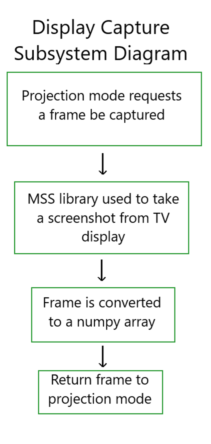
Display Capture
The DisplayCapture class is used for taking screenshots of selected displays, or parts of those displays. It is primarily used in modes which need to modify content visible on the TV before displaying it to the projector, such as Blur, Speed Blur and Low Health. The diagram below explains how these modes interact with DisplayCapture.
Audio Capture
The Wobble mode was designed to be triggered when (a) any loud noise above a certain threshold was heard or (b) when an explosive sound was detected in the audio (to prevent triggering the effect for loud game music etc.). Unfortunately, due to incompatibility between Librosa and Nuitka, the explosive sound detection has not made it into the final compiled build. However, since this feature has already been implemented, it is included in this section. The implementation details for both features are defined in the AudioCapture as follows.
(a) The microphone audio is recorded at intervals. This data is used to calculate a root mean square (RMS) value (to reduce the effect of background noise) and compared against a user-defined threshold. When the RMS value is larger, the Wobble mode is triggered. We considered using a moving average to reduce the effect of short-term fluctuations in the audio however, it was more important for us to identify the intensity of the signal (since intensity is proportional to loudness).
(b) This is how the audio from the microphone is classified using a Convolutional Neural Network (CNN) model:
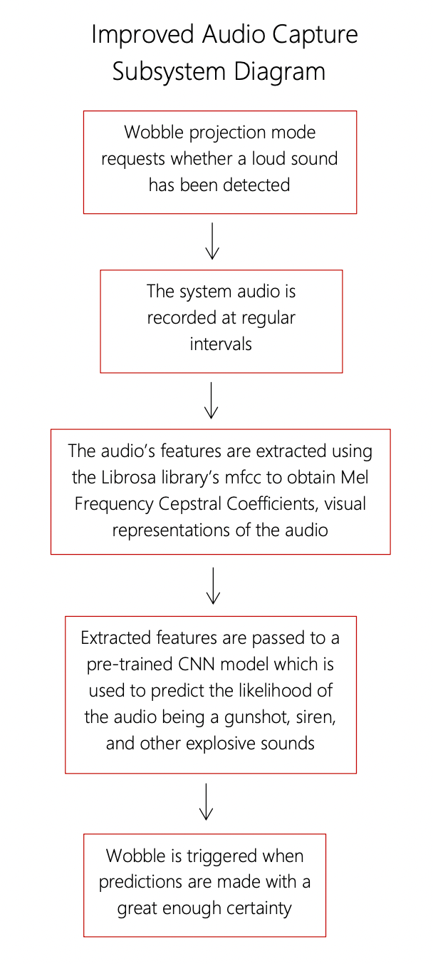
Azure ML Studio was utilised when researching different CNN models to classify the audio input and investigate their performance for our use cases. A virtual machine was used compute the models on ML Studio. We were able to take advantage of the free Azure credits students receive upon signing up to do this. The chosen pre-trained model has been trained on the UrbanSound8K dataset by Mike Smales. The UrbanSound8K dataset contains audio files for gunshots, drilling, sirens and other loud, explosive sounds. Since, it would be most effective to trigger Wobble for such sounds, this dataset and model were selected for our use. The model had a training accuracy of 98% and testing accuracy of 91%. The high scores indicate it has not suffered from overfitting and will therefore, perform better predictions on unseen data. More information regarding audio processing, the model architecture (etc.) can be found in Smales’ report.
Calibration
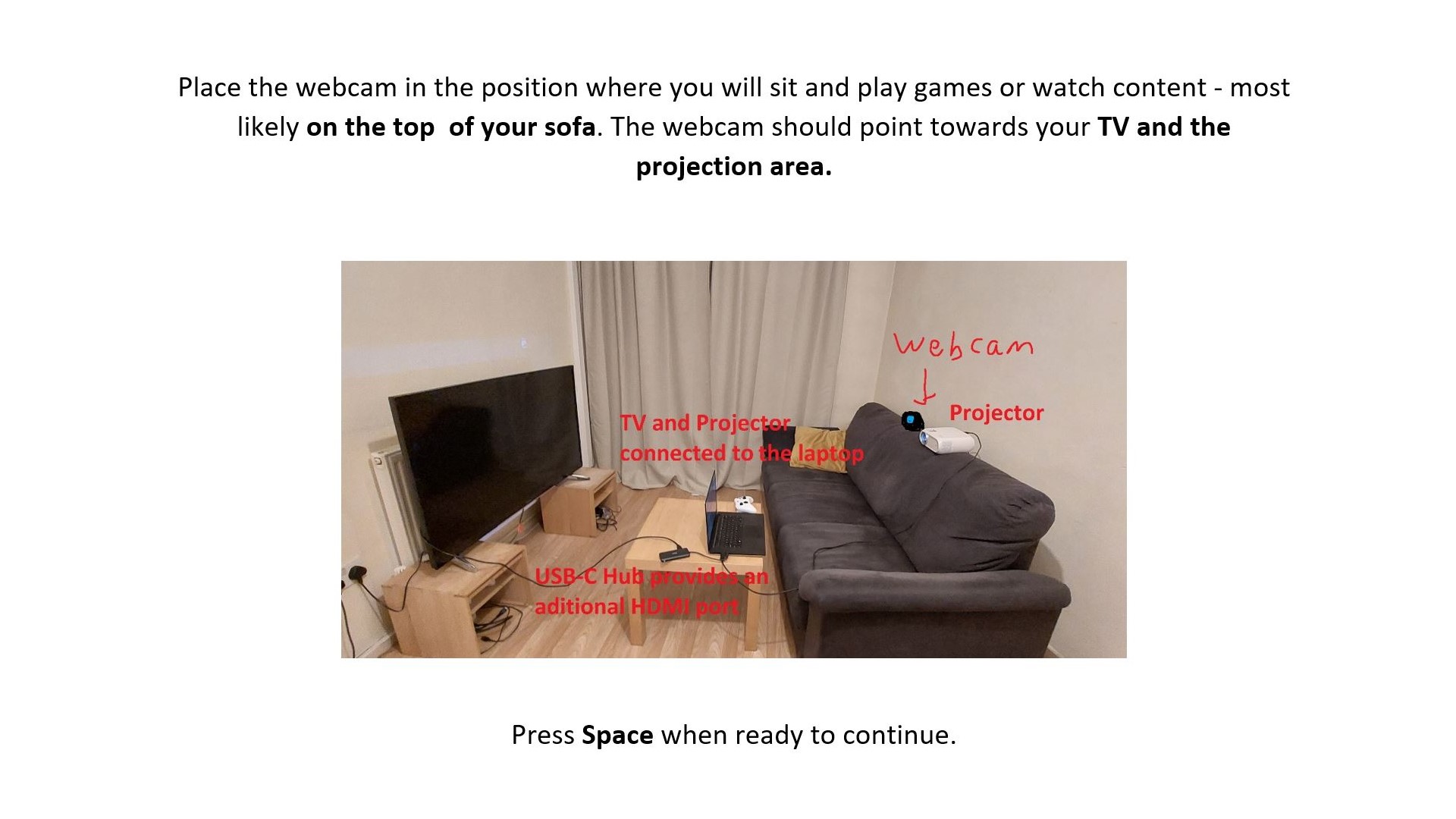
Hardware Setup
The user is walked through the calibration process by the instructions displayed on the TV. They must place the projector facing the TV and the camera in the correct place, close to where their eyeline would be.
Camera Selection
The user is then prompted to select their webcam camera which they can configure using the MFC. At this stage, they will be able to verify whether they have selected the right camera to proceed with for the rest of the system setup.
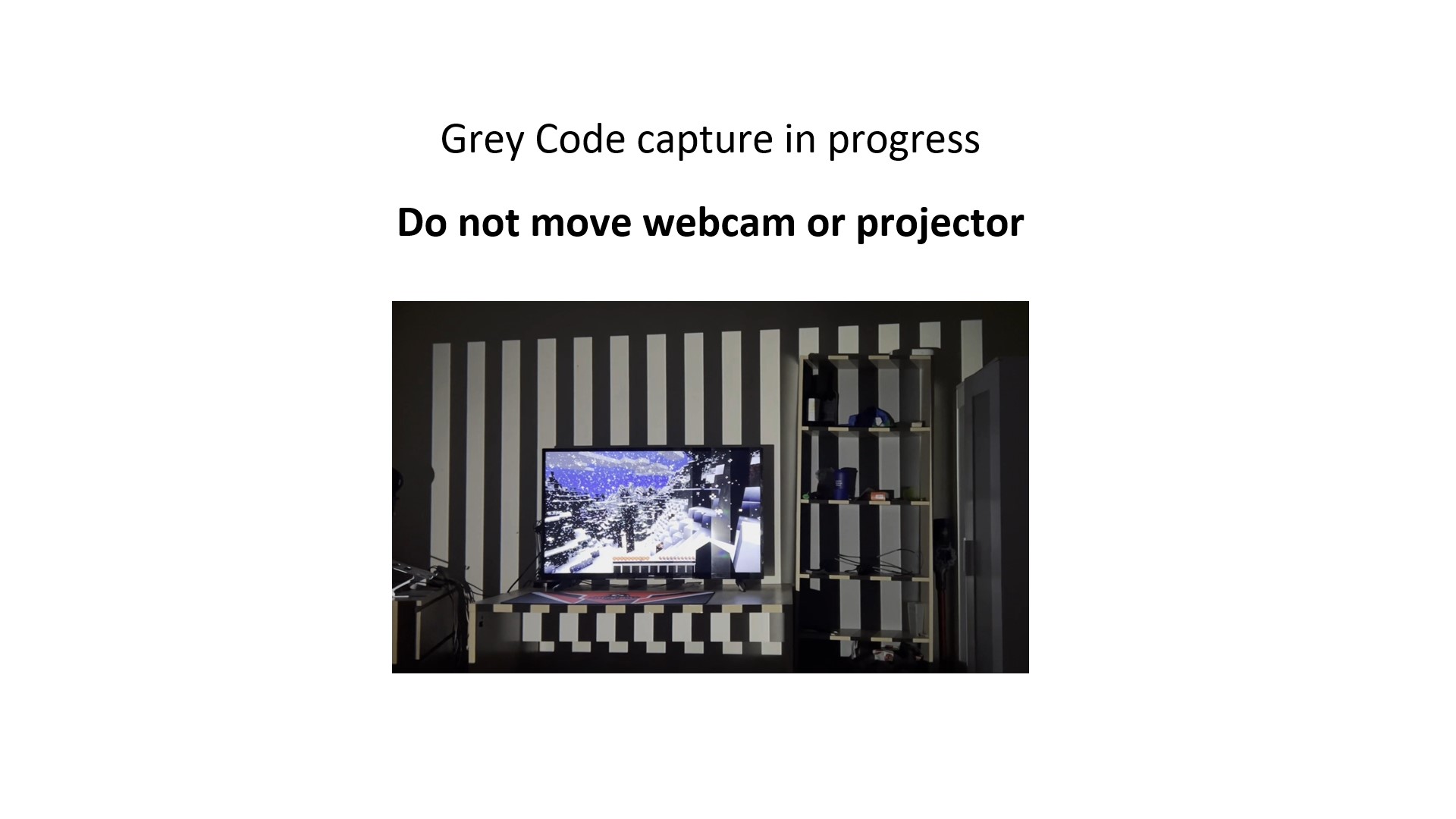
Gray-code Pattern Capture
Following this, the Gray-Code pattern capture takes place. A calibration executable, separate from the main application, is called for capturing these frames. The executable starts a thread that constantly reads frames from that camera and the last frame can be read from the main thread to smoothly capture all patterns displayed on the projector. Once all the necessary frames have been captured, the pattern resolution and images get saved to the assets folder for later use.
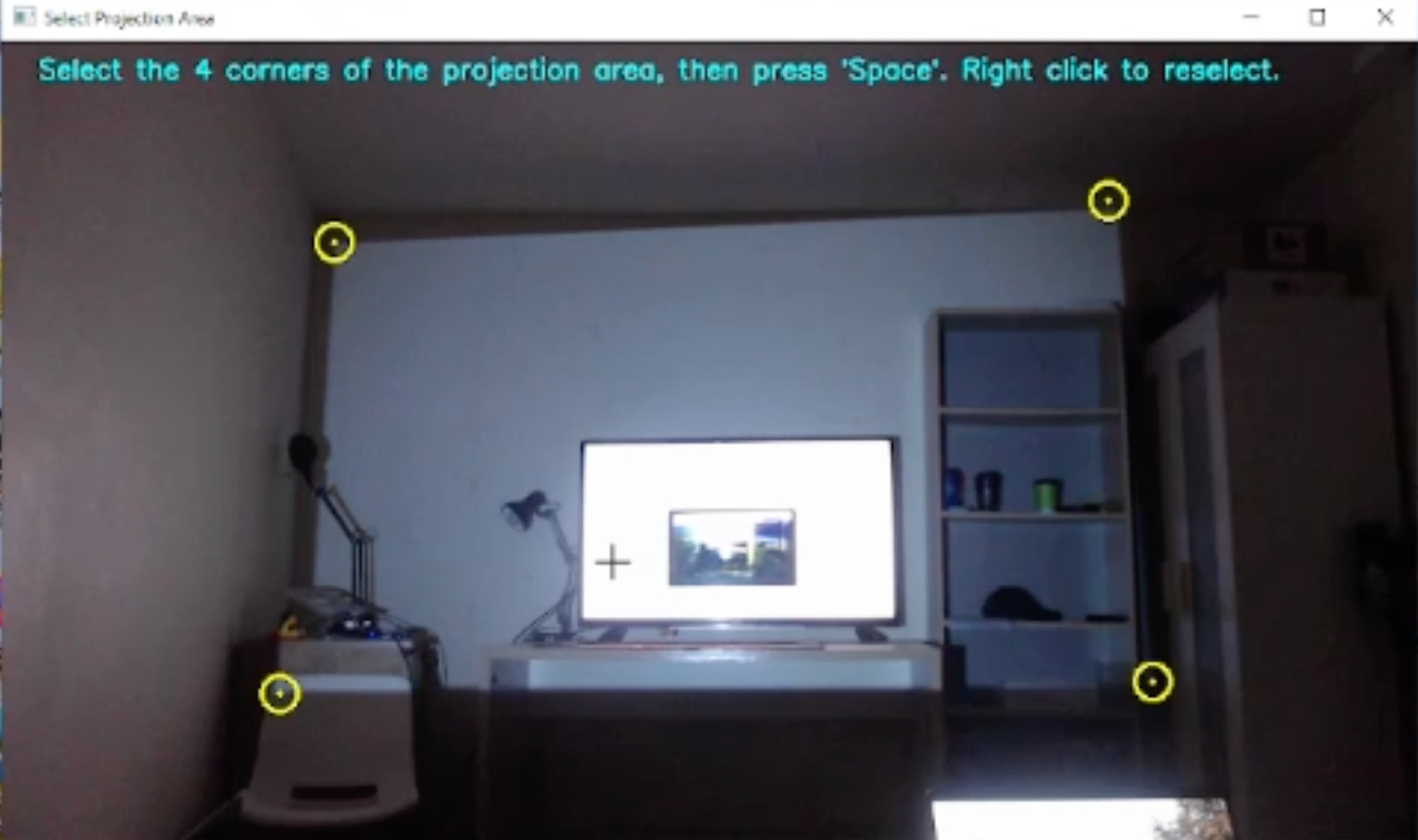
Projection Area Selection
The Software Calibration now begins. A grey coloured frame is shown on the projector’s display so that the selected camera can capture an image of the projection area. This image will be used by modes like Snow, Rain and Wobble to map effects on and apply transformations to the objects within the user’s room.
Early in the project, Microsoft Lens was used to capture an image of the area of projection from the projector’s viewpoint. The cropping featured minimised the effect of the camera angle when the picture was taken and ensured that the image contained only the projected area.
This is how we achieve a similar perspective transformation on our captured image using OpenCV:
- The user is asked to select the 4 corners of the projected image, with the ability to reselect if required.
- These corners are ordered to determine the top left, top right, bottom right and bottom left coordinates by observing the x-value and y-value ascending sorted orders as well as the distance between the corners.
- OpenCV’s
getPerspectiveTransformandwarpPerspectiveare applied on the obtained corner coordinates. This results in an image of only the projection area (from the top-down view).
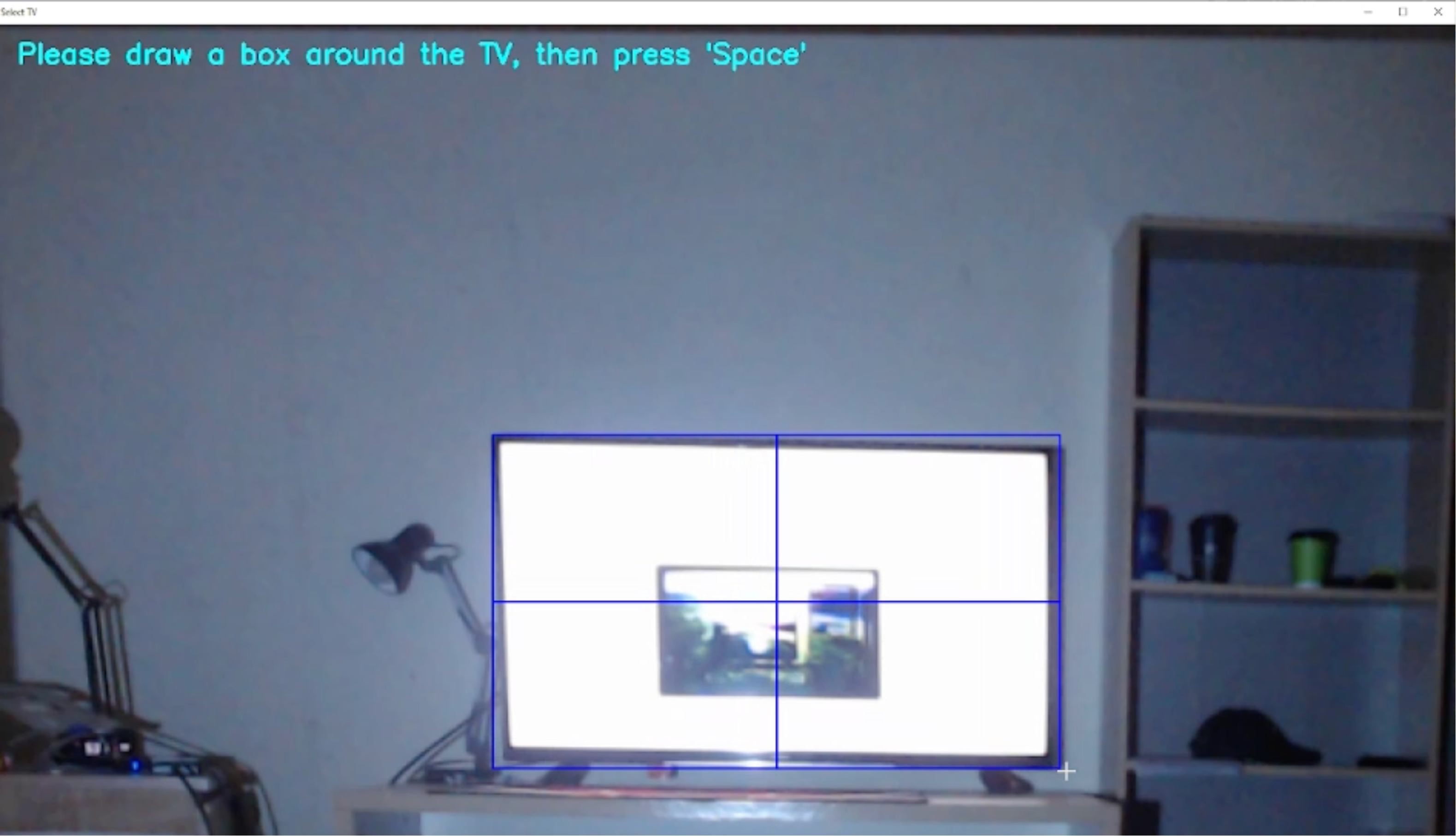
TV Selection
Following this, the user is prompted to select the TV in the image of the projection area. The user is able to draw a bounding box around the TV using OpenCV’s selectROI. The TV’s bounding box is used to create a black mask and this image is saved and used as a background by other projection modes, ensuring that the modes don’t alter this area.
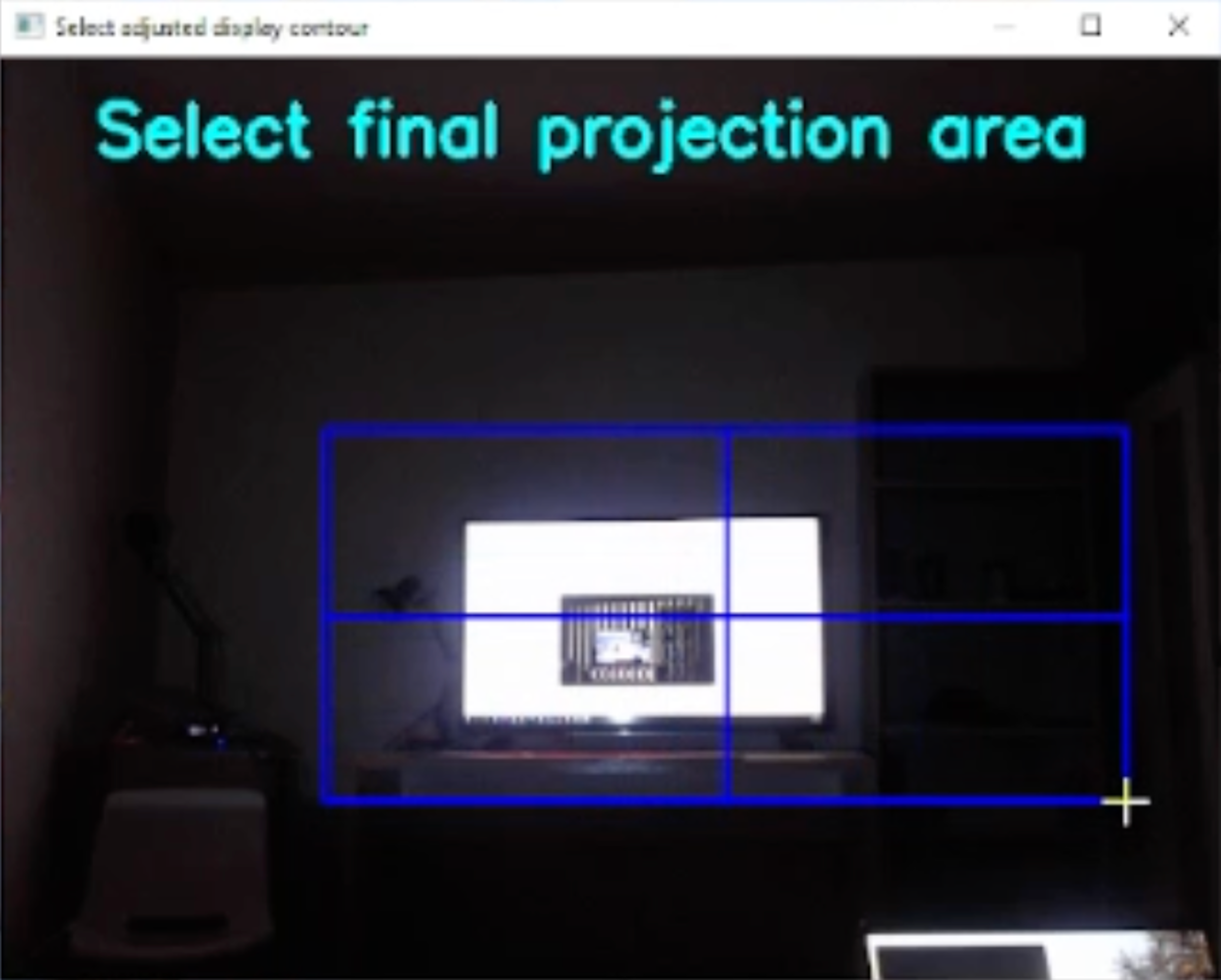
Desired Projection Area Selection
The user is then prompted to select an area they want to display the projection modes on. The calibration executable mentioned in the Gray-code Pattern Capture section is called again with different arguments to use the desired area and the previously captured frames for calibration. After the calibration is finished, 2 maps are saved in a map.ext file to the assets folder. This is used by the DisplayOutput class as explained in its implementation.