Testing
Testing of the Depth Sensing Surgical System
When it comes to testing this system, things can get a little tricky. This is designed to be a surgical system, which means it is dealing with very small distances inside the body; at most around 10 centimetres. However the depth sensor we are using is a Microsoft Kinect 2.0, which cannot measure depth under 50 centimetres. That means that everything has to be scaled up, including the tests that we are conducting on it.
Research Project Concept
This project is essentially a proof of concept - a research project. The end goal is not to have a perfect working surgical system that is ready for deployment once this project is over, it is to prove that a depth sensing surgical system would be viable, is realistic and is useful.
The team’s view is that a depth sensing surgical system would be most useful if it could augment the camera feed to present depth information in an intuitive way. Most importantly, the system should tell the surgeon when a surgical tool in the camera view is getting close to the body tissue, which means that the system would need to identify the tool, measure the distance between the tool and the body and then present the resulting information intuitively, in our case by colouring the edges of the tool based on how close it is the body tissue.
The goal of the project if therefore primarily to show that our system can tell the user when a tool, which in this case would be a larger-than-scale prop, in its view is getting close to the background, which in an actual system would be the body tissue. This is the most important goal and the most important thing to test because if it works, then the concept will have been proven to be viable and useful.
The Props
In order to test any aspect of the system, the team was going to need props. These would need to simulate surgical tools and parts of the body. During early development, the team used very basic props. These consisted of aluminium rods wrapped in green tape which simulated surgical tools as they were about the same size as them. The team quickly realised that larger tools would be needed - because the camera was scaled up greatly from an actual endoscopic camera in terms of size, and was much less accurate over small distances than a depth sensing endoscope would be. In order fully test some of the augmentations, a prop that was not so small would be needed - so the team decided to simply use a bottle wrapped in green tape which was sufficiently large to be clearly visible in all augmentations. The early stage props used are shown below:
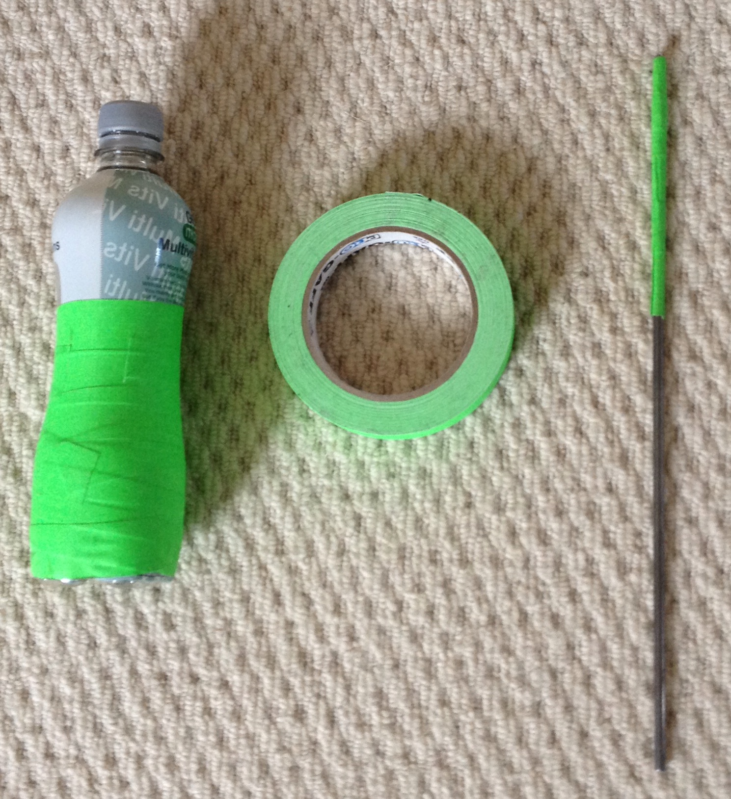
This shows the aluminium rod, bottle and fluorescent green tape used to wrap the tools.
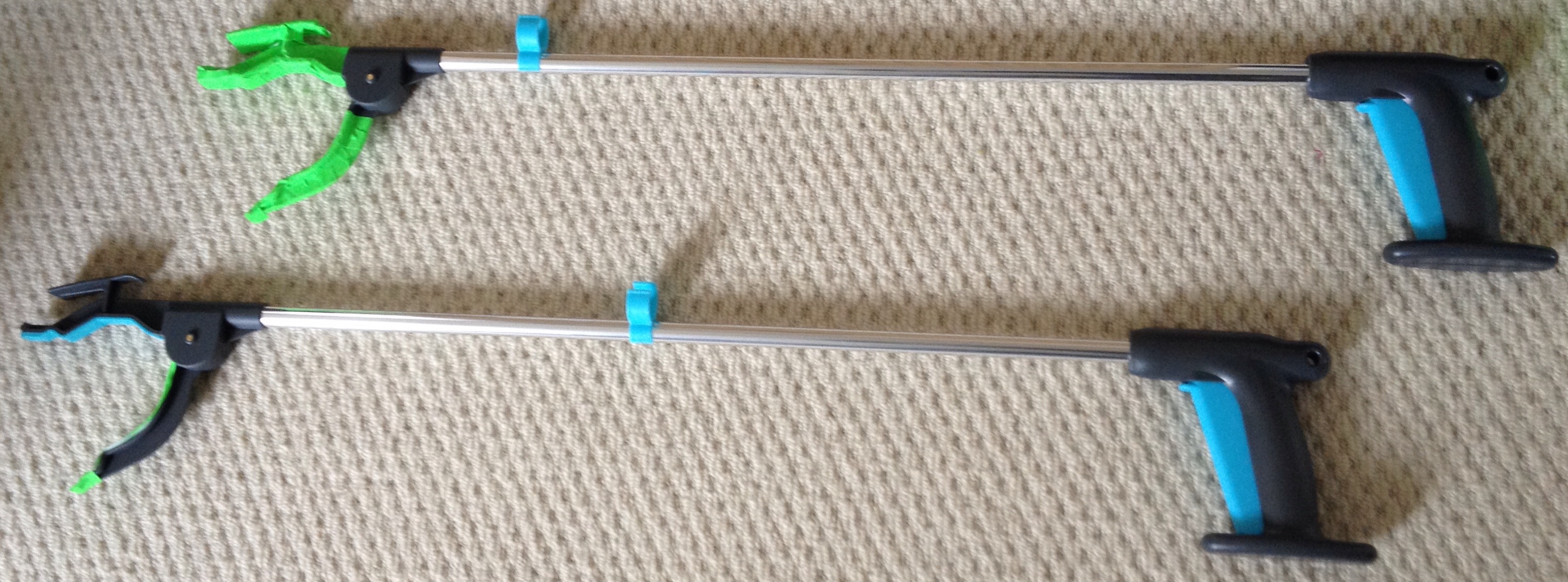
As testing progressed, the team found that more advanced props were needed that actually looked scaled up versions of surgical tools. For these props, the team decided to use reaching aids, which have large claspers on the end which can be used to grasp objects. The claspers of these props were then wrapped in the green tape:
Finally the team needed props to simulate parts of the body. For this, red modelling balloons and red paper was used. The balloons simulate blood vessels and the red paper the general body tissue background. The balloons are shown below:
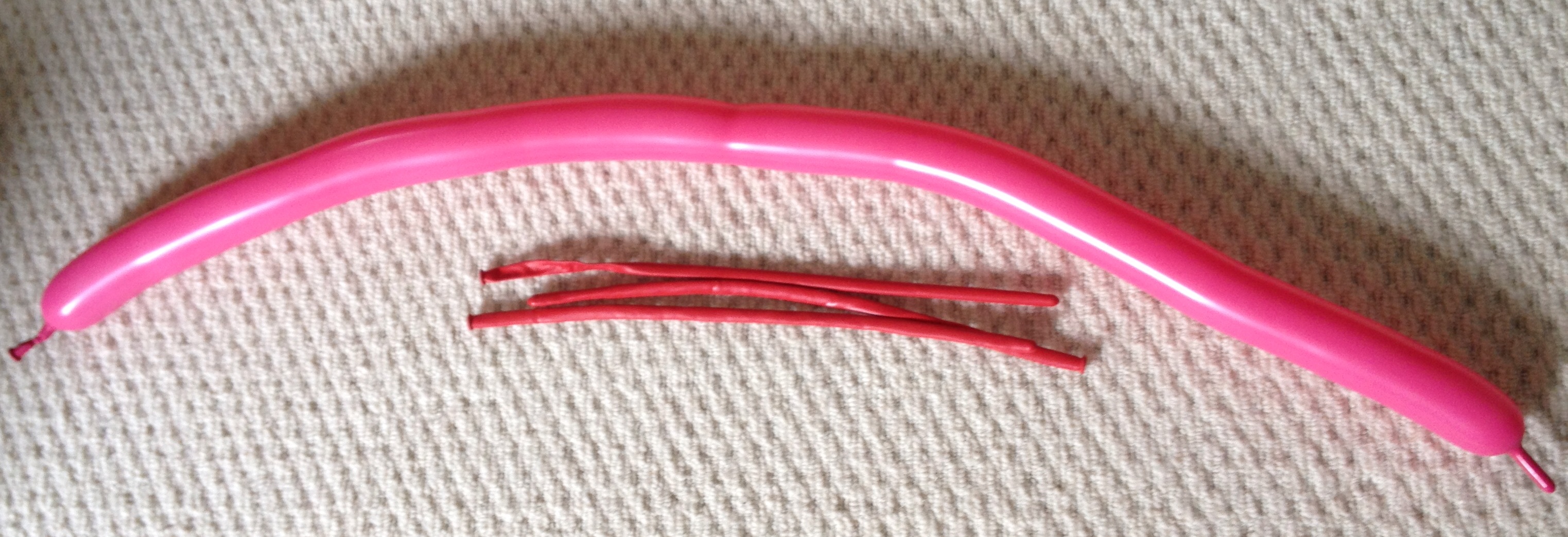
While this is a very basic simulation of the body, it works well enough to demonstrate the system. Building a detailed model was out of the question due to the size that would have to be to accommodate the Kinect’s field of view, but this simple simulation, with red of paper covering a wall as background and red balloons for blood vessels is more than adequate for the proof of concept of the system.
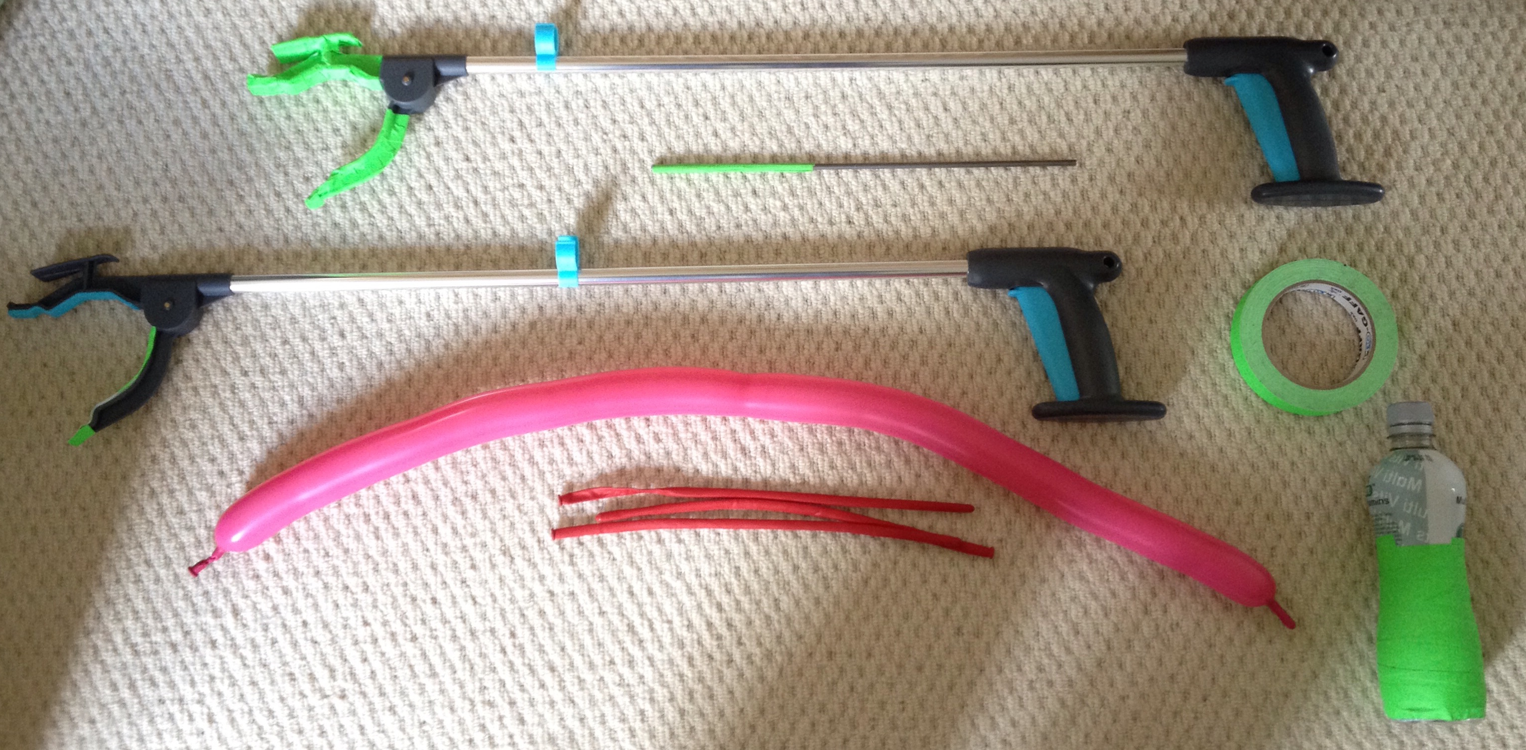
This picture shows all of the props used during testing, not including the red paper used as a background.
Testing Strategy
Bearing the previous section in mind, it can be seen that the most important test to be conducted on this system is whether it can identify a “tool”, and tell what the distance between the tool and the background, such as a wall is. Once this test has been satisfied, then the system can be tested on more interesting scenarios such as “slinging” a blood vessel, described below.
However, before the team could reach this point of testing to test the proof of concept, the algorithm had to be developed in several stages. One of the most important things to do was to identify the tool, which the team was doing by looking for bright green markers that were attached to the props.
Green Tool Identification Test One
This test was simple. The prop with green marker on it would be held in front of the Kinect which was running this tool identification algorithm, and if the algorithm removed all pixels (by making them black) from the image, except the ones that belonged to the green tool, then it would have passed the test. The following image shows the setup used for this test:
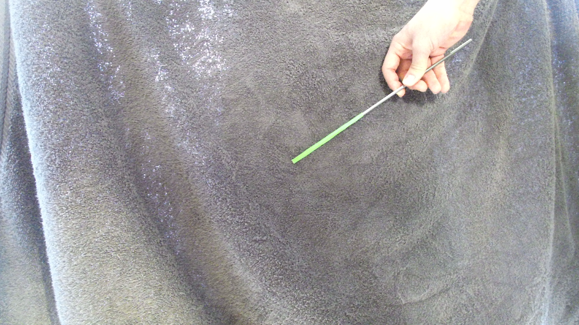
The prop here is an aluminium rod with green tape on one end. When run through the green tool identification algorithm, the following image was produced:
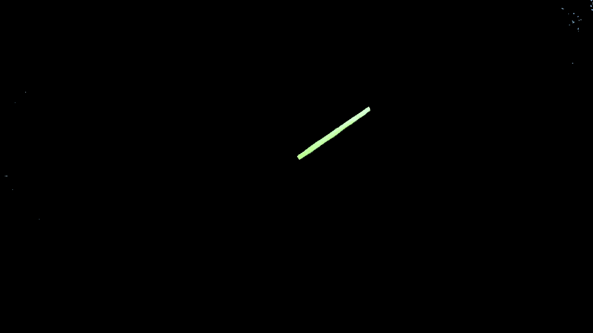
As can be seen, the green part of the tool was identified and all else removed. This test is therefore passed.
Green Tool Identification Test Two
This test expanded slightly on the previous test, simply by adding another object into the background, in this case a notebook. The objective of this test was to see whether the algorithm could distinguish between the green tool and the white notebook, which can sometimes be mistaken for being green due to its high green value. The following setup was used:
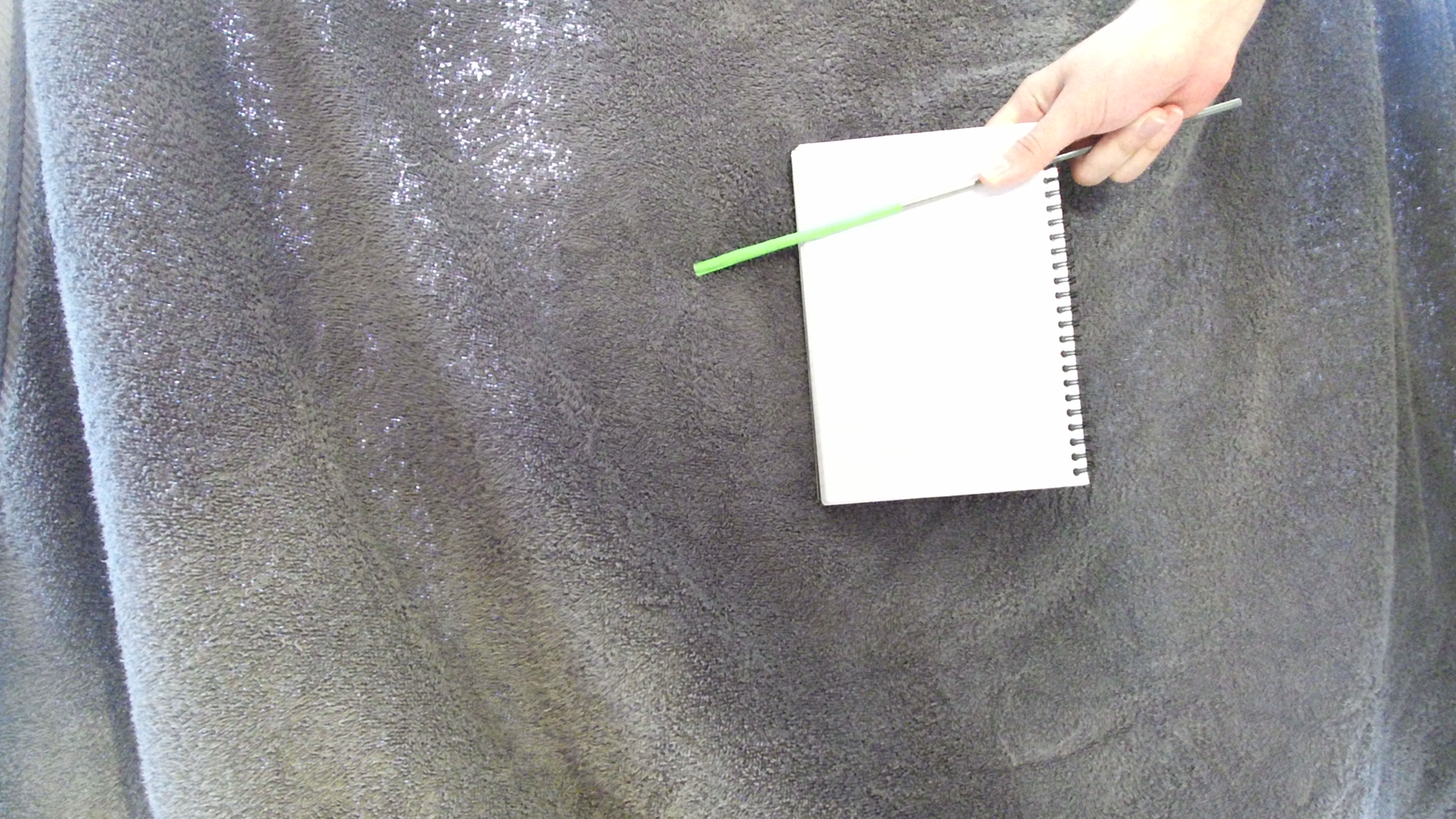
The prop is again an aluminium rod with green tape on it, but there is also a white notebook held behind the tool. Half of the tool is over the gray background, and half over the white, to see if this makes any difference to the identification algorithm. When run, the following image was produced:
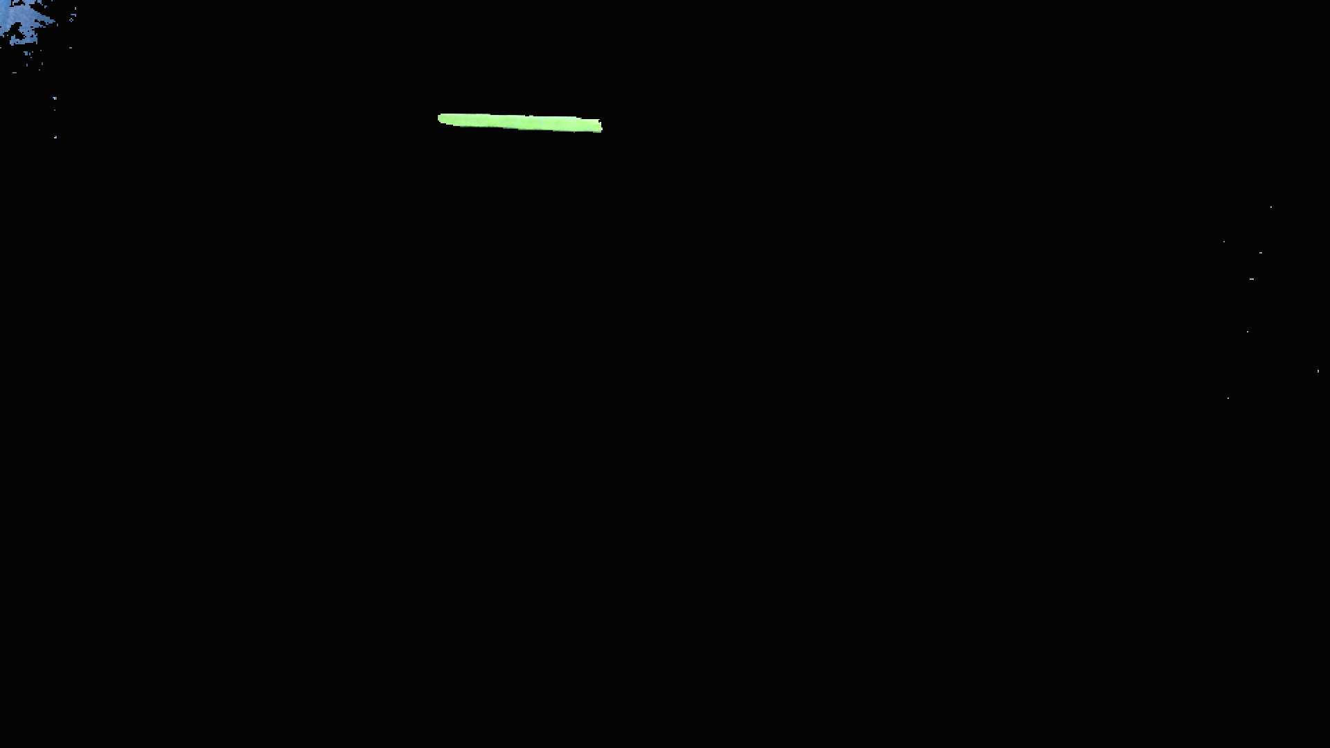
The tool is in a slightly different position in the two screenshots, due to the algorithm running in real time and the tool moving between the times that the two screenshots were taken. Clearly the algorithm was not affected by the presence of the white background, and did not confuse the white as green. There is some noise in the top left hand corner, where light shining through the background is being considered green by the algorithm. However as this is only a small amount of noise and does not disrupt the functioning of the algorithm, the test is still considered to be passed.
Green Prop Depth Test
The purpose of this test was twofold: to test the Kinect’s coordinate mapping function and to test the Kinect’s depth sensing when it came to mapped images. The algorithm being tested at this stage is supposed to print out the depth values, in millimetres, of the green pixels in the camera feed. This needed to be tested because the team were not sure if the coordinate mapping was working correctly, so needed to be sure that the depth values associated with each colour pixel were correct.
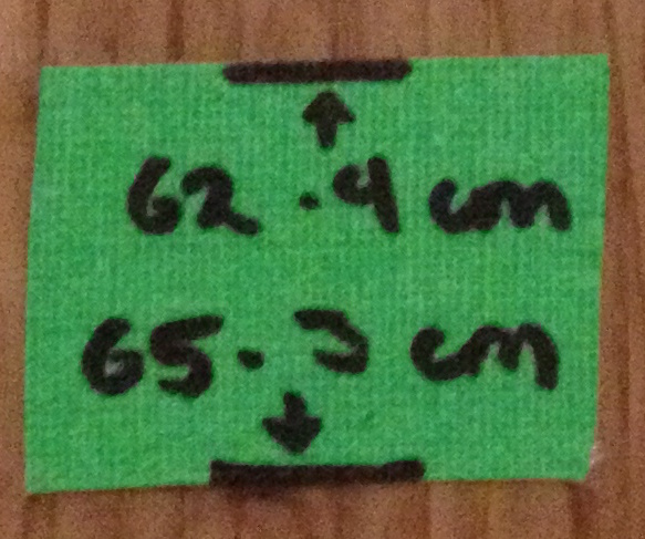
To do this, the Kinect was placed in a set position, and markers measured precisely and placed every 30 centimetres. A green prop, in this case a bottle wrapped in green tape, was then placed at a marker so that its distance from the Kinect was known. The algorithm would then run, map the coordinates of the colour feed to the depth feed, before looking for green pixels using the algorithm described earlier and, if these were found, print out the depth values of the pixel. If these printed values were found to be the same as the measured distance, then the test would be passed. Below is an image of the test setup and a distance marker:
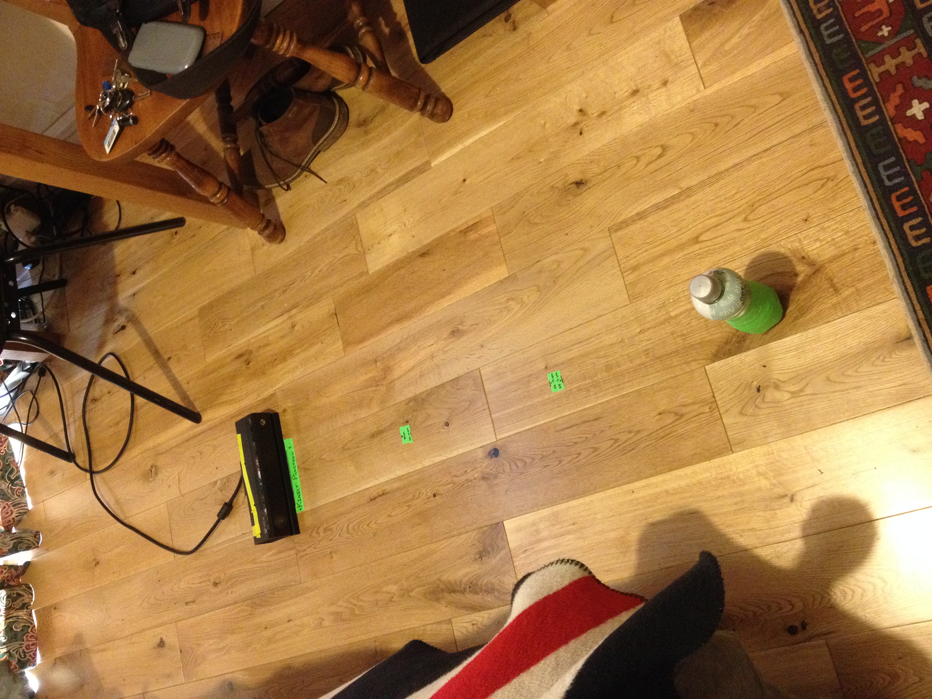
The green prop was placed at a distance of 93 centimetres from the Kinect. When run, the program printed depth values in a range from 930 (mm) to 970. These values are approximately in the range of the bottle, and their variation could be due to pixels being measure on one of the curved surfaces of the bottle. The test is therefore passed.
ToolProximity Augmentation Test
Testing now progresses to the most important parts of the system. This test is extremely simple, but possibly the most important test conducted. This test will determine whether the ToolProximity algorithm is working.
If the augmentation is working, then the edges of the green tool should turn orange when the tool is close to the background, and turn red when the tool is touching the background. The test therefore is quite simply to move the green tool back and forth in front of the Kinect, and monitor the augmentation displayed on the laptop screen. If the edges of the tool turn red when it touches the background, then the augmentation is working correctly. Below is a picture of the result of applying the algorithm:
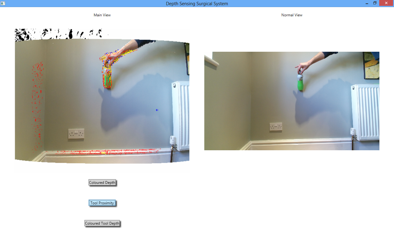
As can be seen, the augmentation works correctly. However the colouration of the edges is extremely granular and noisy. As documented in the Development section, a second version of the ToolProximity augmentation was created which is simpler than the one shown here but is more reliable as this one requires more development before deployment, unfortunately the team has run out of time to continue this development. The following screenshot is of the same test being applied to the second version of the ToolProximity algorithm:
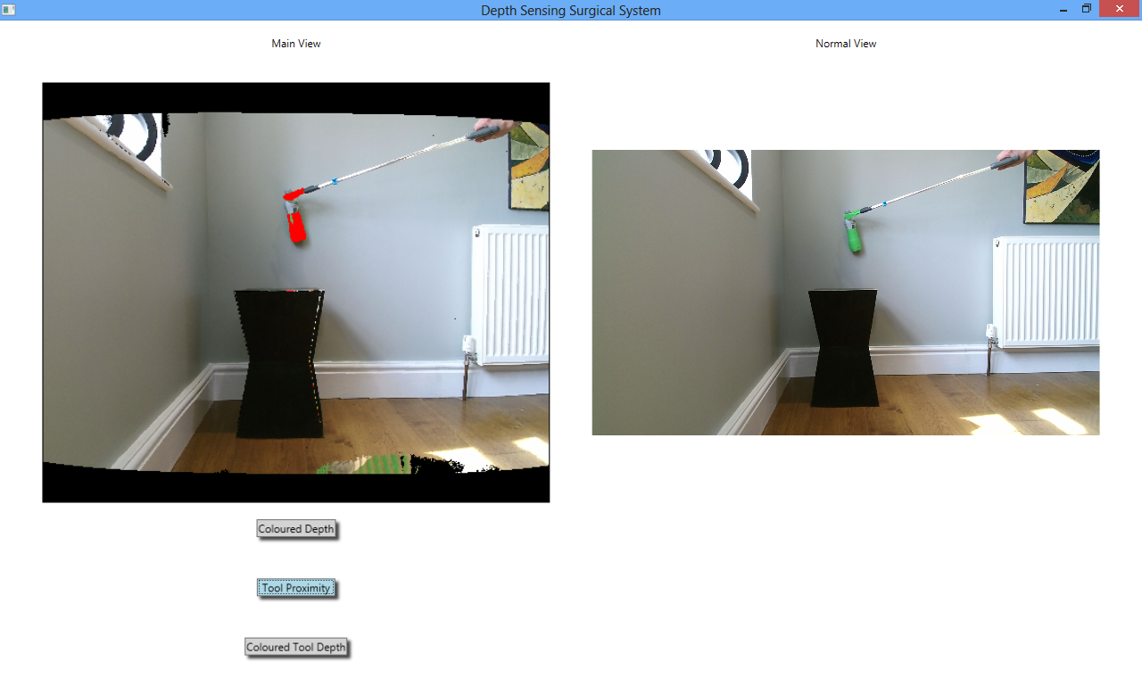
Clearly the test is also passed for this augmentation, the tool turned red just as it was about to touch the wall in the background.
ToolProximity to Other Tools Test
This test was also extremely simple - to see if the ToolProximity augmentation would change the colour of the grabber arm in the picture above red as it got close to the bottle, which was placed on the small black table.
Unfortunately, this did not work. The algorithm is not advanced enough to be able to tell proximity to other foreground objects, only the back ground. If the ToolProximity augmentation that relies on edge finding were sufficiently developed, it would be able to do this due to the nature of its algorithm. However the algorithm is not fully developed so is not fit for this purpose currently.
This test was important, because it illustrated to the team how the ToolProximity algorithm would best be used: when a cutting instrument such as a diathermy tool is approaching body tissue that the surgeon wishes to cut through. The augmentation would be most useful here because the tool would turn red as it gets close to the body tissue, telling the surgeon that they should reduce the force being applied to the tool because it is now close to the tissue.
Proximity Between Tools Test
An important capability of the system is that it be able to tell the surgeon whether two foreground objects are the same distance away from the camera. The test devised for our system to check whether it could do this was to place the green bottle on a table, and then looking at the screen of the system, attempt to pick up the bottle using the grabber arm.
The team found that the best augmentation with which to complete this test was ColoredDepth. As ToolProximity does not work for this test (explained in the previous section), the user can instead tell when two objects are the same distance from the camera by judging when they have turned the same colour (which corresponds to their depth).
The outcome of this test was that the team could always tell when the grabber arm was approximately inline with the bottle, although occasionally when the claspers were closed the bottle was knocked over rather than grabbed. If the tool were a few centimeters closer to the bottle, then it would not have knocked it over but clasped it, yet the tool still looked to be the same colour as the bottle at this point. This is not an issue that would be of importance in the actual system, as the Kinect is not particularly accurate over small distances (which a depth sensing endoscope would be) so missing the bottle by a few centimetres does not mean that the test was failed. With a more accurate depth sensor, it is unlikely that the bottle would have been knocked over at all.
Voice Control Testing
The voice control test was simple. Speak the commands that affect the system (“tool proximity on”, “tool depth on”, “colored depth on” and respective “off” commands) from a range of different distances, and if the augmentations change on command then the voice control is working.
Voice control was tested up to 3 metres away, and worked well at all distances provided that the user spoke clearly. This is not an unreasonable requirement, and as commands did not often have to be repeated to get the system to react, the test is considered a success.
The main issue with the voice control system noticed during these tests was that there is no indication of whether the system is currently listening for commands, or what the commands are if the user forgets them. These would be things to add on a next iteration of the system: a small icon that is highlighted when the system is listening for voice commands and a small button that when pressed reminds users of the different commands that can be uttered to control the system.
Scenario Design
After these tests, a slightly more advanced test needed to be designed for the system that simulated objects such as blood vessels. On recommendation from our client, the team decided to use the scenario of “slinging” a blood vessel to test the system. This scenario is where a surgeon uses two claspers to pass a piece of string around a blood vessel and then pull it out of the way so that they can get a clearer picture of what they are doing. It is a procedure performed often in laparoscopic surgery, so one that it is important to check the system can help the user with.
To create this scenario, the team will use the two grabber arms, a piece of string and a long, thin red modelling balloon which will simulate a blood vessel. This will be conducted on a background of red to simulate background body tissue.
The setup for the “slinging a blood vessel” scenario is shown below:
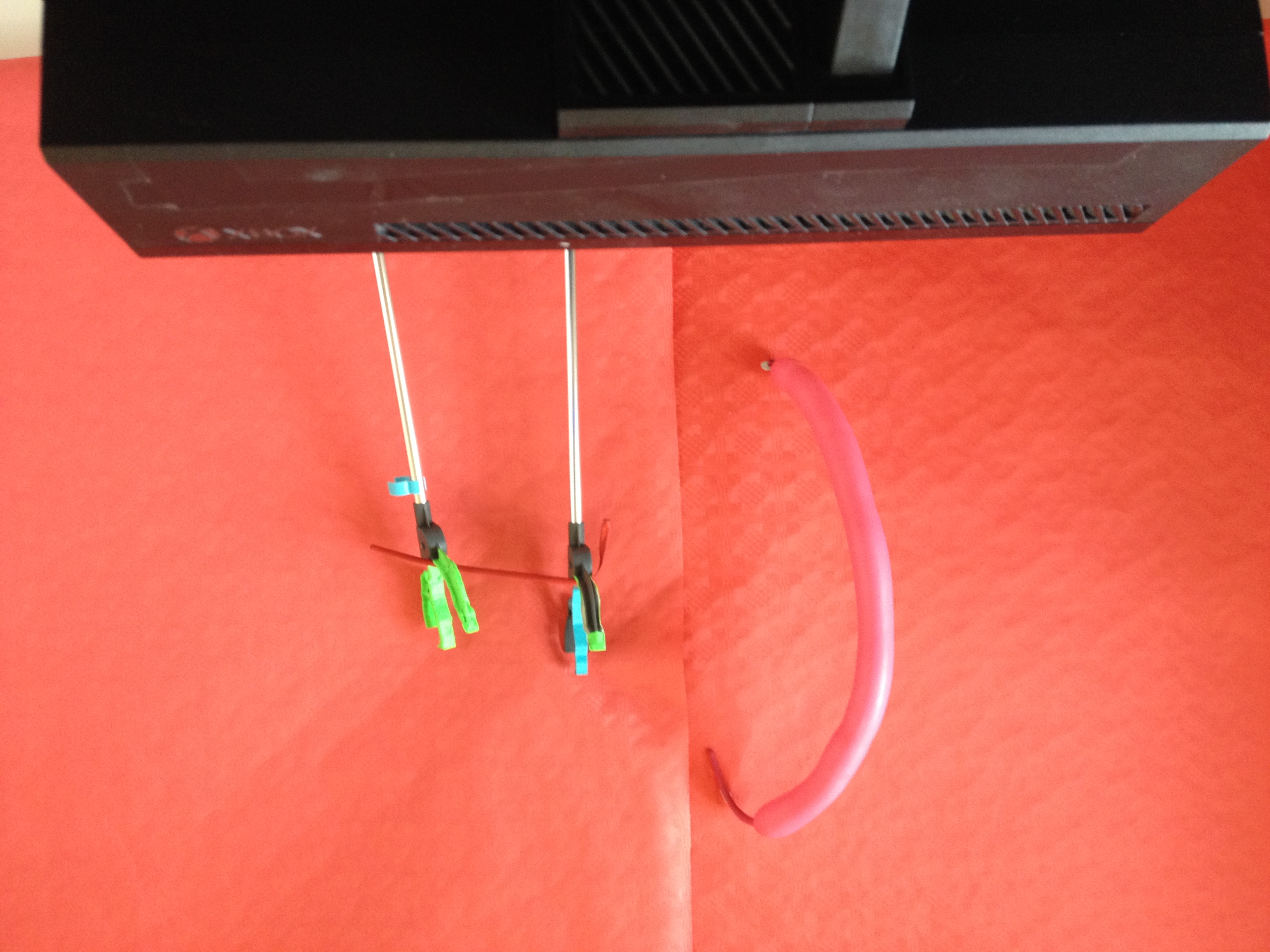
The Kinect sensor can be seen in the foreground, with the props used to construct the scenario in the background. The wall is covered with red paper that provides the general background of red body tissue. On this is blu-tacked a red modelling balloon that simulate the blood vessel to be slung. The two grabber arms used to simulate surgical tools can also be seen, and the material used to sling the “blood vessel” which is another, deflated modelling balloon. Below is a video that shows that shows this test being run:
The test is conducted by looking at the screen that is displaying the feeds from the Kinect, and then attempting to hook the deflated modelling balloon around the “blood vessel”. If this can be done without having to look away from the screen, the test is considered passed. This test was passed, and as it was the most advanced test, holds the most weight in terms of judging the success of the system.
Based on the fact that all important tests shown above were passed and the advanced test of slinging a blood vessel was passed, the system is judged to be a success.